I admit it: I'm a total geek. I love electronics, programming, 3D printing, 3D art, and vintage Apple hardware. I'm always juggling half a dozen projects. I also enjoy documenting it all: my successes, my failures, my experiences... and everything geeky along the way.
I was originally going to use an IR remote and receiver to control the GPS clock that I'm working on. I just wasn't happy with the way that it worked after I had prototyped it and implemented the code. I decided to use buttons instead.
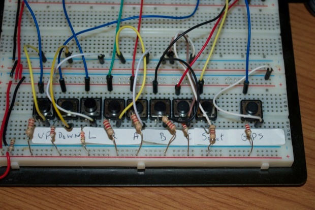
I ditched the IR receiver and wired up a few buttons to my Arduino. I wrote the code for them, but soon realized that I needed another button for "SELECT". I went to my parts boxes, dug out another button and a 2.2K resistor. I then wired it to my breadboard and continued with the code.
Soon enough, I needed yet another button for the GPS menu, then another to do a manual sync. Back to the parts boxes. Once I had all the features implemented, my button count had grown to 9. I needed to break out a second breadboard just for the buttons. Nine buttons, 9 resistors, 18 jumper wires.
There has to be a better way to quickly (and neatly) add a bunch of buttons to my breadboard for prototyping! Not to mention keeping extra buttons handy in the event I might need them for prototyping seems wasteful.
I came up with the idea that it would be cool to have a little button breakout board that I could quickly pop on to my breadboard when I suddenly found myself in need of some buttons. Instead of scrounging for buttons and resistors and taking up a whole ton of space, I could just simply connect a "mini keyboard" to the breadboard and be up and running in seconds.
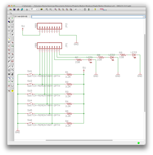
I jumped into Eagle and chalked up a schematic for a mini board with 6 mini push buttons and 3 LEDs. The LEDs aren't necessarily for the buttons. All 6 buttons as well as the LEDs are all broken out to a 9-pin header. I don't know what I'll use the LEDs for, but it'll be nice to be able to use the LEDs for status. When I push a button, I could have my code turn on one of the LEDs so I know that a function was called. Basically a small board with some simple I/O for rapid prototyping.
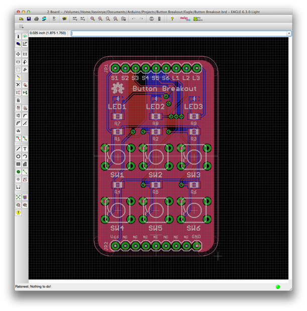
The PCB is very small and shouldn't take up much space at all on my breadboard. The top header connects to the 6 buttons and the 3 LEDS. The bottom header is for Vcc and ground and serves to keep the PCB level on the breadboard.
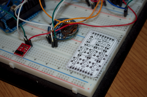
I printed out the PCB to make sure that it'll fit on my breadboard with enough row clearance on either side to connect jumper wires to both headers. It's perfect. It takes up a fraction of the space that the individual buttons did. Granted, I was using 9 before and this board has 6, but when you place an order with OSH Park, you get 3 PCBs. In theory, I should be able to quickly and neatly add up to 18 buttons to any project.
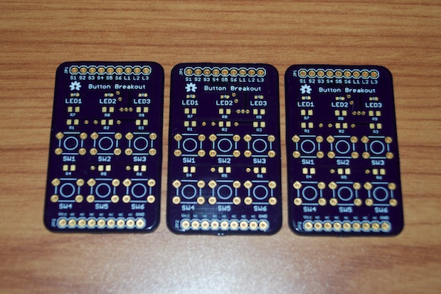
I placed my order with OSH Park and had the PCBs in-hand in a week. That was really fast. In the past, the PCBs have taken about 2 weeks. They must have sourced some addition fab houses after they acquired the BatchPCB business.
The boards look great. The color is deep and the text is crisp.
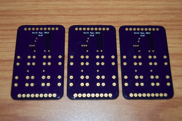
Nothing fancy on the back; just my name, date, and the version number.
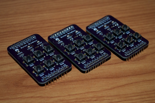
I usually do a walkthrough of the assembly, but it's just 2 headers, 6 buttons, 9 resistors, and 3 LEDS. No big deal. I had all 3 boards assembled in about an hour; and that was with a few interruptions.
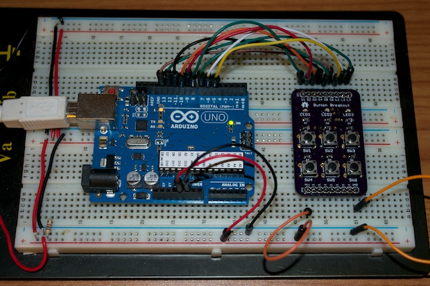
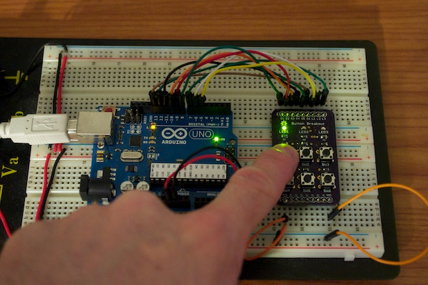
To test them out, I popped them onto my breadboard, connected the buttons and LEDs to my Arduino and chalked up a quick sketch.
Here's the sketch. Nothing fancy; I just have the buttons light up the LEDs when pressed just to make sure that everything works.
int l1 = 5; int l2 = 6; int l3 = 7; int s1 = 8; int s2 = 9; int s3 = 10; int s4 = 11; int s5 = 12; int s6 = 13;