I admit it: I'm a total geek. I love electronics, programming, 3D printing, 3D art, and vintage Apple hardware. I'm always juggling half a dozen projects. I also enjoy documenting it all: my successes, my failures, my experiences... and everything geeky along the way.
I finished the code for the clock. I would have been finished a week ago, but Hurricane Sandy hit my town pretty hard and I lost power for 8 days. What a setback. Anyway, power’s up and it’s full-steam ahead!
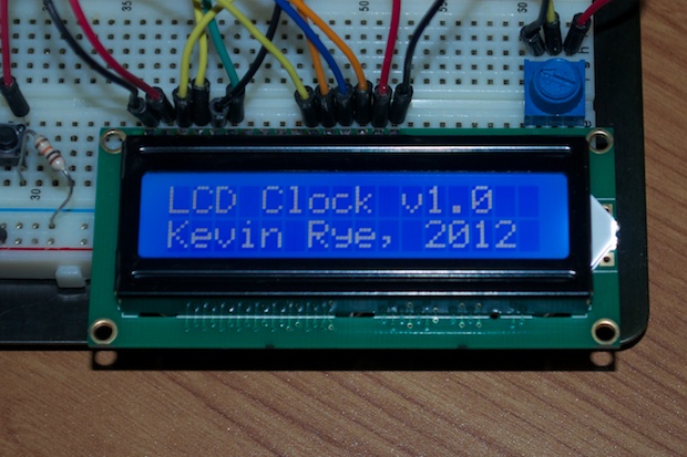
When I left off, my clock looked like this:
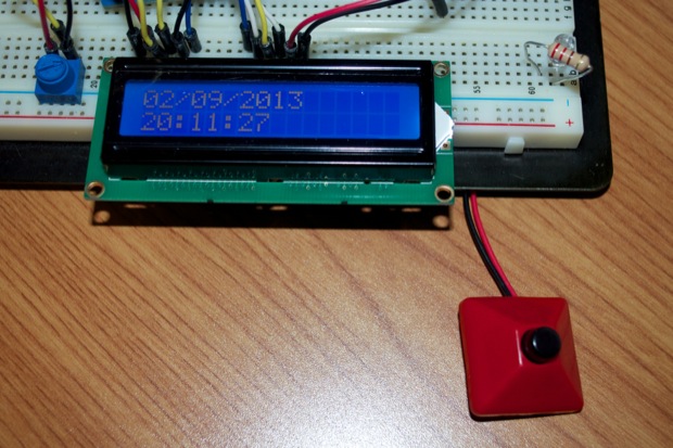
After a few hours of tinkering, I managed to figure out all that the Crystal Library has to offer. I flip-flopped the time and date, as well as centered all the text. The time is now on the top and the date is on the bottom. I also figured out how to display the day of the week. I even got it to display a splash screen when it first powers up.
Now that everything looks good, it’s time to figure out how to set it.
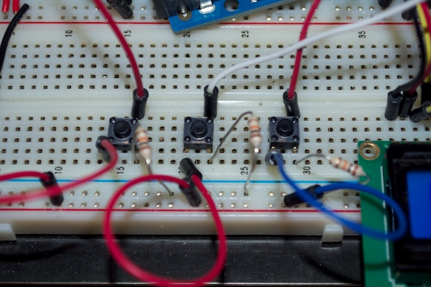
After figuring out how to key off a button press, I rummaged through my parts box looking for some switches. I have more switches that I can count, but nothing that’s a momentary-close with 4 pins that would be good for my breadboard. I found some really nice 12mm switches on SparkFun that I wanted to use on the final project, but I didn’t want to wait a week for them to come in to resume prototyping. I dug a little deeper in my parts box and found an old broken portable CD player that I was saving hoping that the motor assembly would come in handy one day. I torn it open and was very pleased to see that the switches underneath the front panel were exactly what I was looking for. I unsoldered them from the PCB and popped them into my breadboard.
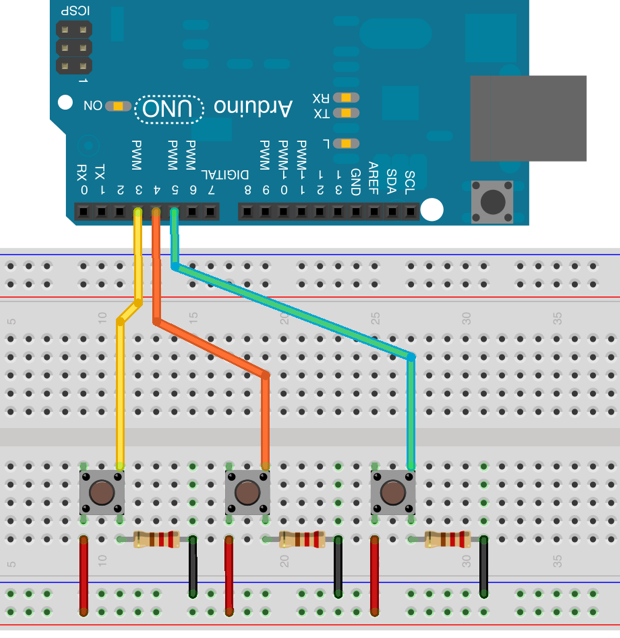
To debounce these switches, you tie one lead of one side to ground and the other to Vcc. On the opposite side of the switch, you make a connection to your input pin on the Arduino. That 4th leg on the input side doesn’t need a connection. Here’s a better looking diagram:
I have one switch connected that puts the clock into set mode. Once in set mode, the hours section will flash. Each subsequent press of the set button will step you through each settable field on the clock: hours, minutes, day of week, month, day of month, and year. Once you get to the year, pressing the set button again takes you out of set mode. The other 2 buttons will either increment or decrement the field that is flashing.
Originally I had 4 buttons. One to enter set mode, a “next” button to step through the settable fields, and two to increment and decrement the fields. With a little code wizardry, I managed to combine the “set” and “next” buttons. I realize that I can get it down to 2 buttons if I illuminate the “down” button, but I hate clocks that make you wrap around if you miss your number. So three buttons it is: SET, UP, and DOWN.
Here’s a video of it in action:
I’ll have to tweak the code again before all is said and done. My seconds seems to skip here and there. I have too many delays in the code. If it takes more than a seconds to run through that main loop, the time will skip a second. So that needs to be reworked. I’ll post the final code when the project is complete.