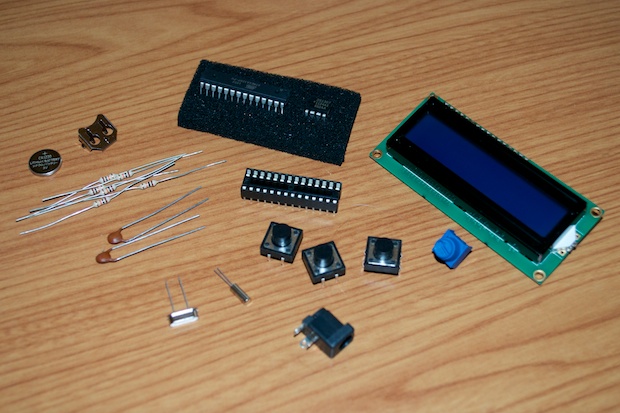
With the clock code complete, it was time to hop online and order my parts. With the parts in hand, I’ll have an easier time laying them out on the PCB and getting the spacing right.
As far as designing the board, there are many options available. I’ve used
Express PCB in the past, but their boards look pretty plain and boring, and are pretty expensive for what you get.
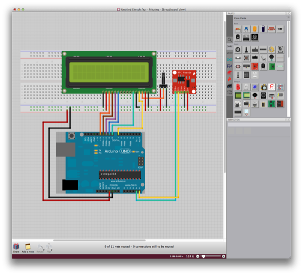
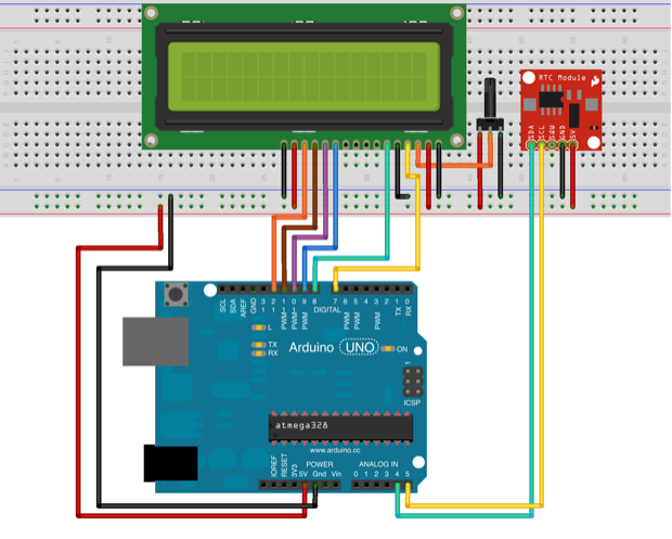
I recently started played around with Fritzing. It’s a pretty cool free utility that lets you lay out parts on a breadboard.
It’ll then automatically create a schematic for you...
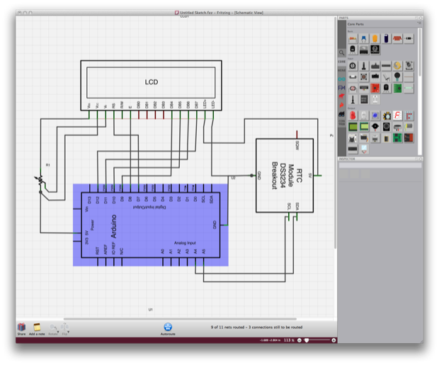
…as well as a PCB.
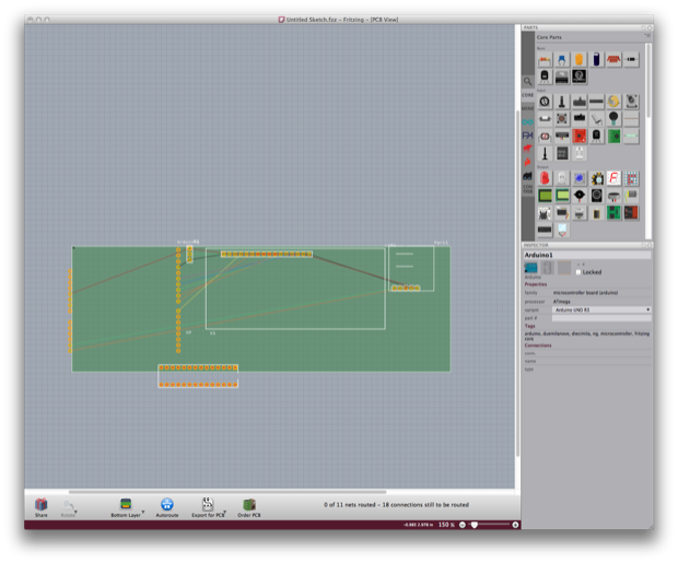
All you have to do is run your traces. You can also let it autoroute it for you.
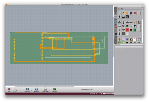
From there, you can generate Gerber files to send them out for PCB manufacture. It’s really a one-stop-shop. The boards come out of Germany, so they are a little expensive. Still, it’s a really useful utility. If anything, it makes for nice screen shots when you’re doing “howtos”.
Fritzing is really cool, but I wanted to give Eagle a try since it seems to be the most commonly used PCB design tool around. Most blogs that I’ve read all seem to agree that Eagle is the de facto standard when it comes to PCB design. The “pro” version is expensive, but they do offer a free version that’s more than adequate for what most hobbyists need. Also, popular Arduino retailers like Adafruit and SparkFun have downloadable Eagle Libraries for all of their parts.
I downloaded Eagle and ran the installer. Once it was up and running, I loaded in the Adafruit and SparkFun libraries.
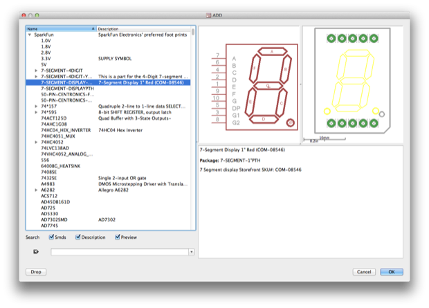
I then dropped in my components and started chalking up a schematic based on my prototype.
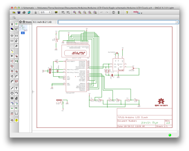
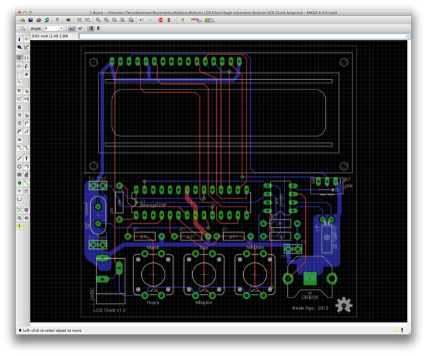
Once complete, I flipped over to the PCB file and all my components and connections where automatically generated. I then mapped out all my traces and ground planes.
I wasn’t sure how the final product was going to look. I couldn’t decide if I wanted to have the components and LCD on one side, or have the LCD on one side and the components on the other. The clock is probably going to be mounted in some sort of clear enclosure or stand so that you can see the guts. Having the components and the LCD on one side will let you see it all without having to flip it over. Overall, it might make for a better presentation.
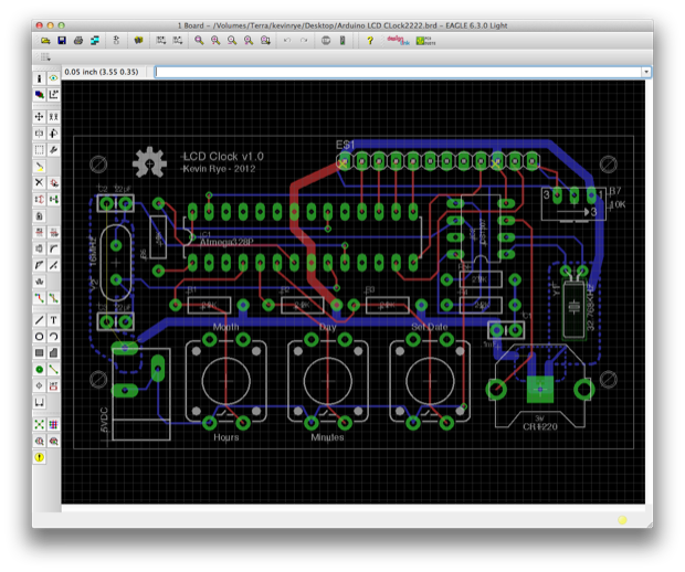
I also designed a compact version by putting the LCD on the back. By doing so, I effectively cut the PCB in half. That should be a huge cost savings when it comes to having the board made.
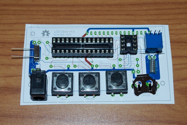
I then printed out the PCB so I can lay my parts out on it.
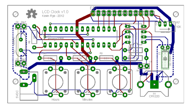
Everything was adequately spaced. So it looks like I’m on the right track.
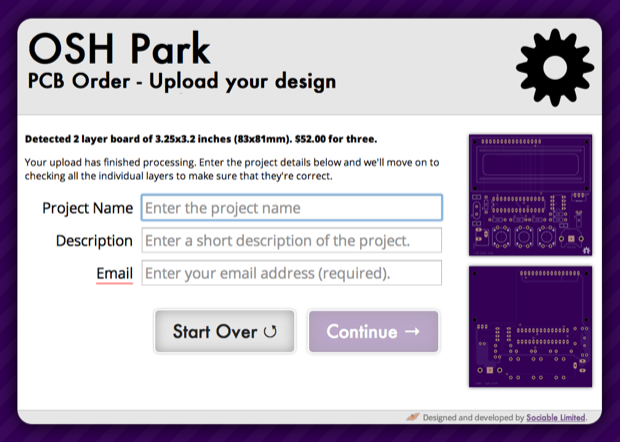
Since I can’t decide between the large and the small designs, I decide to upload the files to
OSH Park and see what the price difference would be. OSH Park makes some really cool looking purple PCBs. The pricing is great and everyone raves about the board quality.
I uploaded the large board and was quoted a price of $52.00 for three 3.25” x 3.2” boards.
Going with the small board, the price would be $30.50 for three 3.3” x 1.85” boards.
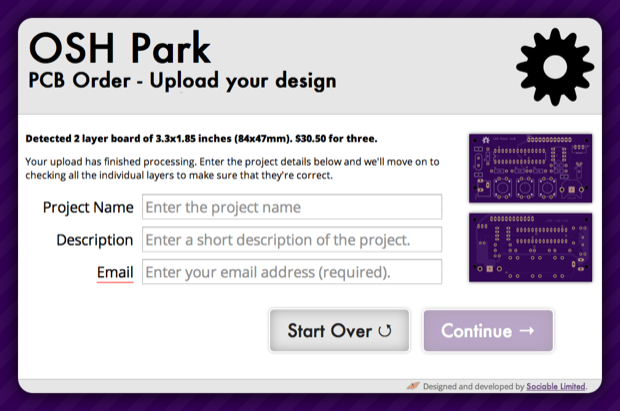
Doing the math, that’s $17.33 each for the large vs. $10.17 each for the small. That’s quite a difference!
I still can’t decide; both look great for different reasons. Although the small board would be $7 cheaper, it’s not really a matter of saving a few bucks. I’d rather spend a little extra than compromise on the design. Having a small compact clock might look really cool mounted on an angled piece of acrylic, but I’m also throwing around the idea of running the clock off a battery as opposed to an adapter. If I shrink the board down and attach a battery pack, the battery pack might dominate the clock. Where would I even put it? I’m not going to sandwich it between the boards. I’d have to make the stand bigger, which totally defeats the purpose of giving the PCB a small footprint. At least if the LCD and components are both on one side, people can see the PCB and I’ll have better access to the buttons. In addition, I’ll be able to mount the battery pack on the back behind the LCD.
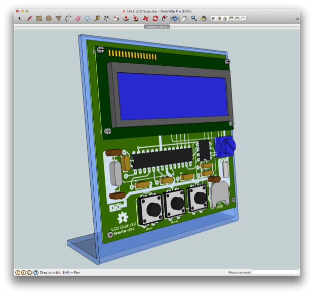
To help me decide, I chalked up some Google SketchUps. Here’s the compact version:
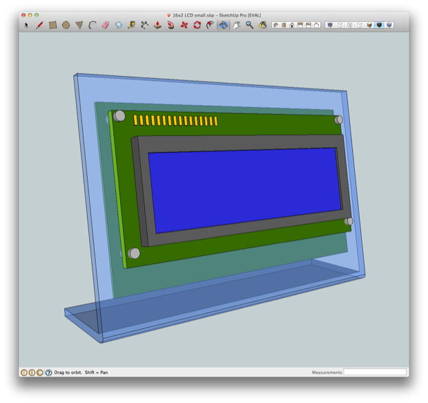
Although it’s compact, all the guts are on the back. No one is gong to see them. It might not be readily apparent that I designed it. I want this to be an eye catcher, so it has to look a little home-brew. Also, being so tiny, I think it might look silly with a power cord hanging out the back. The weight of the power cord might pull it around the desk. I can see it never wanting to sit straight. I’d hate to have to put rubber feet on it. Also, setting it might be awkward with the buttons on the back. Although it looks really cool, I just might have to go with my original idea of putting everything on the front.
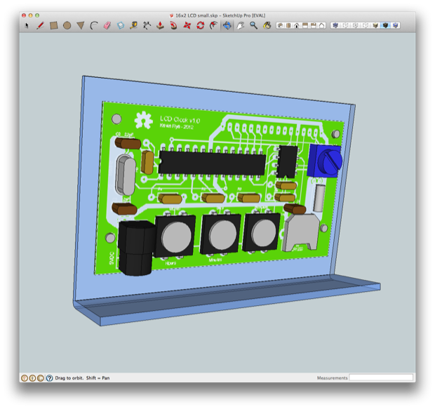
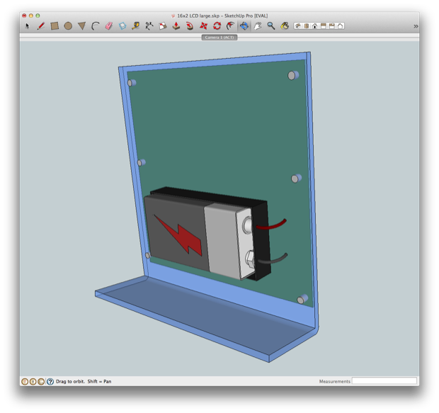
It’s not perfect, but you get the idea. If I put the LCD on the front, I’ll have space on the back to conceal a 9 Volt battery pack. The additional weight from the battery might also help stabilize the base.
I attached a 9V to my breadboard and connected it to a 7805 5V regulator. The bad news is that my circuit pulls 330 mA. The 9V was dead in about 30 minutes. AAs would last longer, but not by much. It looks like I’ll be sticking with an adaptor.
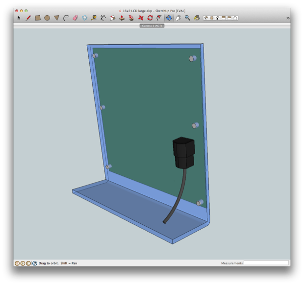
The DC jack is actually mounted on the back of the board, so I updated the SketchUp to reflect that.
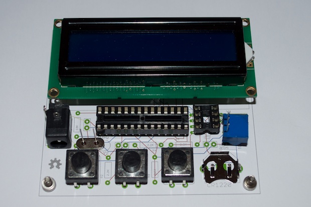
I printed out the PCB and laid my parts out to check the spacing.
I built the entire circuit on the breadboard without the Arduino to make sure that everything works. I had some trouble getting the DS1307 to accept the time. I tried two chips and they just don’t work. For now, I’m sticking with the breakout board from Adafruit.
Overall, I’m not really happy with the DS1307’s performance. What I read online was true. The DS1307 is good for time stamping, but not time keeping. In the case where you just need to keep track of an hour or a day, the DS1307 will do fine. If you’re actually interested in minutes and seconds, the DS1307 just isn’t accurate enough. The accuracy of the RTC depends on several factors; one being the quality/accuracy of the 12 pF crystal on pins 1 and 2. If you’re using a crystal with a loose tolerance, your clock isn’t going to be accurate. It can also lose several minutes a day depending on how the temperature changes. I’ve noticed that the time on my clock skips seconds here and there. After 48 hours of operation, my clock had drifted 4 minutes. Unacceptable.
I decided to shop around for a new RTC. I’m going to go with the better DS3231. The DS3231 is way more accurate than the DS1307. It also has an internal crystal that compensates for temperature changes. The data sheet says it’ll only drift by +/- 1 minute a year. That sounds perfect.
I hopped online and picked up a few DS3231s and a breakout board. Hopefully they arrive by the weekend. I’m eager to try it out and rework my Eagle file.
Once I nail that down, things should move along smoothly since I now have a pretty clear vision of how the board should look.
See this project from start to finish: We Have a Clock Setting the Clock Clock Code is Complete Clock Design Decisions
New DS1307 Kit ChronoDot Breakout Board Arduino LCD Clock PCB Complete Making the LCD Clock Stand - Take 1 Arduino LCD Clock PCBs Arrived! Arduino LCD Clock Assembly Making the LCD Clock Stand - Take 2 Another Clock Stand Arduino LCD Clock: New GUI Laser Cut LCD Clock Enclosure: Take 1 Laser Cut LCD Clock Enclosure: Take 2
