In my
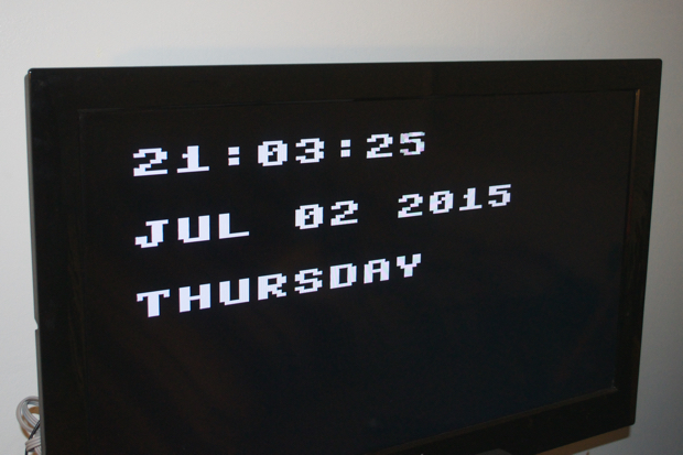
last post, I left off with a pretty good looking proof of concept for my TVout project. I successfully figured out how to use the TVout library to talk to my TV and display my custom "gui" showing the date and time.
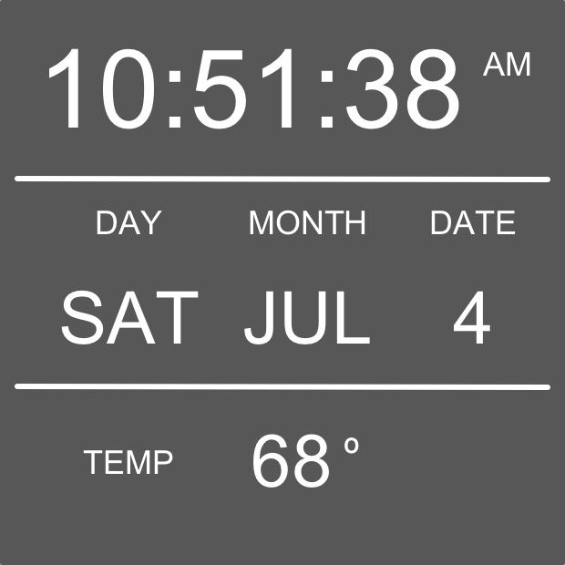
Seeing that this was totally doable, I jumped into Pixelmator and chalked up a reference image showing exactly how I wanted the display to look. Something like this:
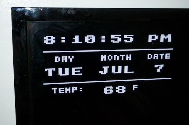
An hour or two later, I had something that was pretty close. The TVout font library is limited to just a few choices. If I really want to get the font size of the time any larger I'm going to have to roll my own fonts.
That kept me busy until my vintage JVC camcorder viewfinder arrived in the mail. I found this baby on eBay for $20 bucks with free shipping. Score!
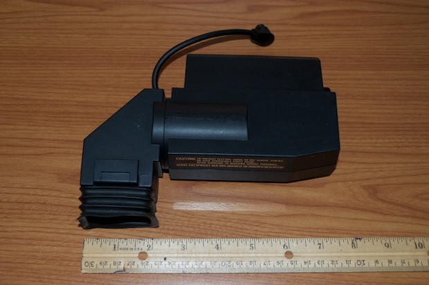
It's a little bigger than I had imagined. It's almost 8 inches long. It's actually good that it is as big as it is. It might not only make it easer to work with, but it'll be that much easier to see the time and date on a the 1 1/8" CRT.
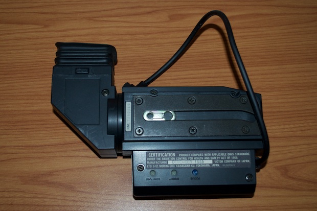
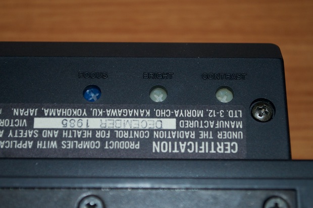
There's also some pots on there to tweak the focus, brightness, and contrast. This CRT is indeed vintage! It's dated 1985.
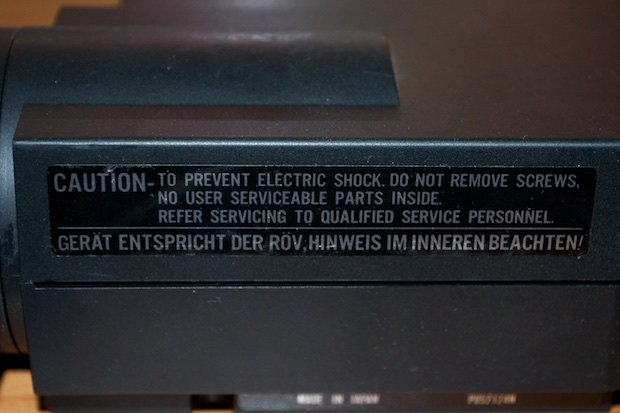
Qualified Personnel? Please. Challenge accepted!
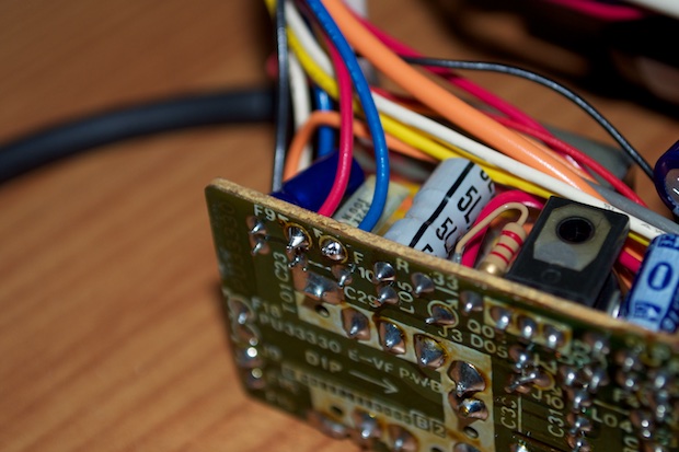
I cracked it open to see what I was dealing with. Pretty cool stuff.
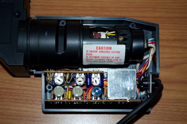
I removed the holder for the CRT to take a closer look. The tube measures 4 1/4" from end-to-end.
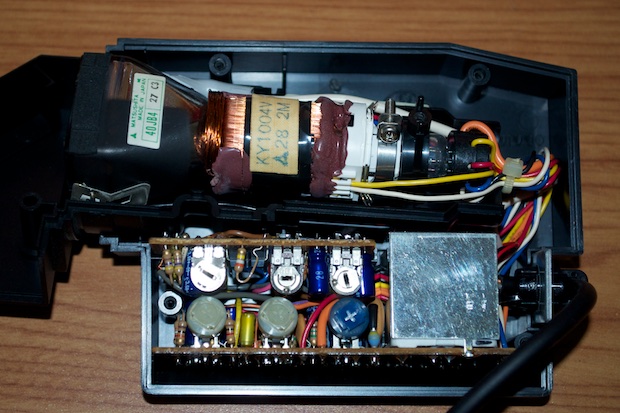
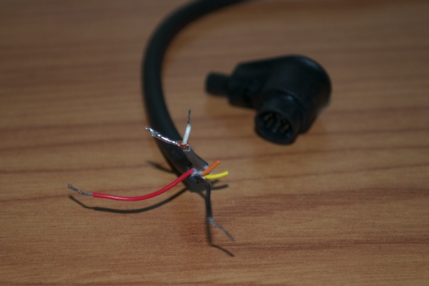
The connector has 8 pins, but only 5 wires come out the other end. In order to find out what was what, I cut the connector off. Red and black are obviously positive and negative. The gray wire is the only one that's shielded, so it has to be the composite video lead. The yellow wire doesn't make it out the other end, so it's probably just a ground. The orange is probably a signal wire for low battery or something.
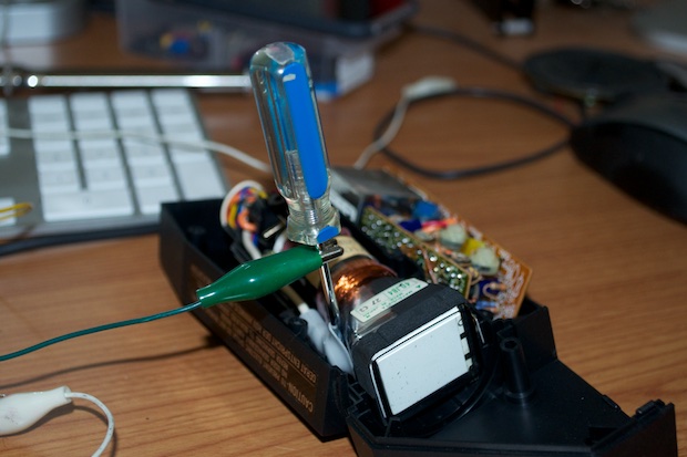
I pulled out my trusty
DIY power supply and hooked up 12 volts to the black and red leads.
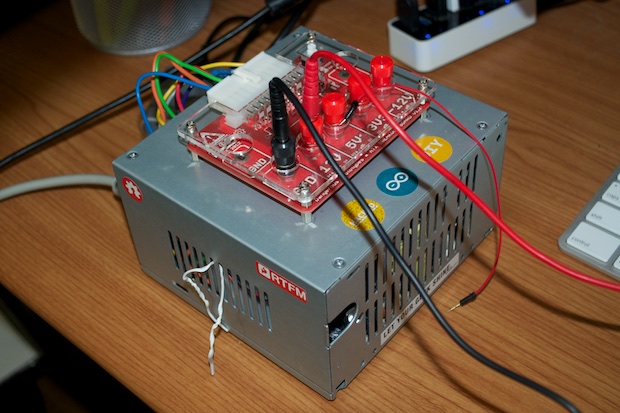
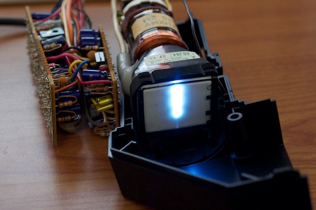
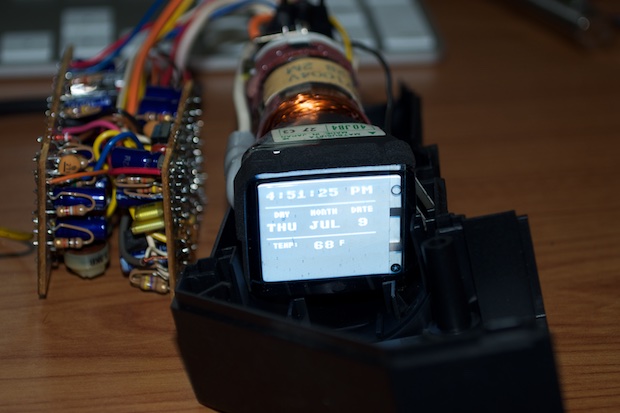
Woo ha ha! We have power! After a second or two, the CRT lit up.
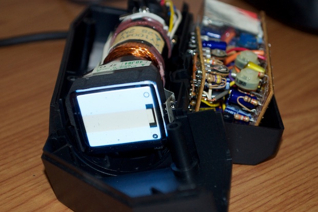
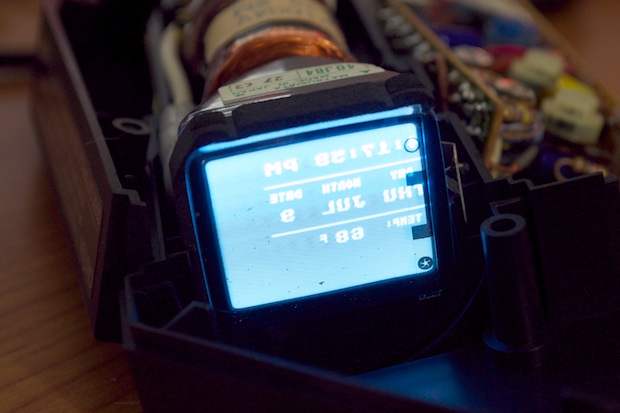
It was then just a matter of applying a video signal from the Arduino. I grounded the shielding on the gray wire and connected the video out from the Arduino to the center lead on the wire. It works. Sort of. It needs a few tweaks. For starters, the image is backwards. It also needs to be centered a little more, but that's just a matter of updating the code
When you look through the viewfinder eyepiece, you're actually looking at the CRT through a mirror that's positioned at an angle. That's why the image is backwards on the CRT.
Most modern CRTs bleed out through a resistor at power down, so they're not storing an extremely high voltage that can lead to a nasty shock. It’s a common misconception that tubes hold upwards of 15,000 volts after you've unplugged them. Maybe this was true back in the "old days". In any case, even if it was storing 15,000 volts, the current is in microamps. It's not enough to light your eyes up. It’ll hurt like hell, but
probably won’t kill you.
With that said, I still don't take my chances. What if the manufacturer skimped out on the design and didn't put in a resistor? Or what if the resistor is open or defective in some way? Better to be safe than sorry. Discharge your CRTs!
In order to flip the image on the CRT, the horizontal deflection wires need to be reversed. It's easy to figure out which are horizontal and which are vertical. On every CRT, there's four wires coming out of the side of the tube; two horizontal and two vertical. If you remove one of the wires and you still have electrons firing vertically, then you disconnected a horizontal deflection wire. The same is true in the other direction. If you remove one of the wires and you still have electrons firing horizontally, then you disconnected a vertical deflection wire.
I traced these two red and blue wires to the PCB. There was a white and yellow wire on the other side. It's one or the other. This pair just seemed easier to get to.
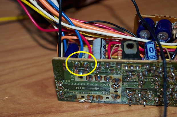
I unsoldered the blue wire. Looking at the CRT, the screen is still being drawn vertically, so I successfully disconnected a horizontal deflection wire. Lucky guess!
To flip the screen, I unsoldered the red one, and soldered them both back in the opposite positions.
Nailed it. I then tweaked my code to push everything over a few pixels.
Now it's just a matter of making some custom fonts, designing a PCB for the video interface, and making a cool enclosure to house the whole thing.
See this project from start to finish:
CRT Clock, Part I CRT Clock, Part II
CRT Clock, Part III CRT Clock, Part IV CRT Clock Case
