I admit it: I'm a total geek. I love electronics, programming, 3D printing, 3D art, and vintage Apple hardware. I'm always juggling half a dozen projects. I also enjoy documenting it all: my successes, my failures, my experiences... and everything geeky along the way.
It’s time for a new clock. While the first clock I made was nice, it wasn’t exactly “display in the living room” material. The project box I used was very ugly. Also, I wasn’t thrilled with the “no-frills” time settings circuit either. Also, the clock had a tendency to bounce if it was plugged into a noisy outlet.
The second clock made had a better time setting circuit, but again, my choice of project box left something to be desired. A box that I ended up never finishing.
It’s time to create a new clock. One that looks as good as it runs. Ideally, I’d like to have it in some sort of clear enclosure to showcases the “guts”. I also want to uses a crystal this time instead of relying on the 60 Hz line signal. I also want to implement a better time setting circuit. I am also going to make this one with blue LEDs.
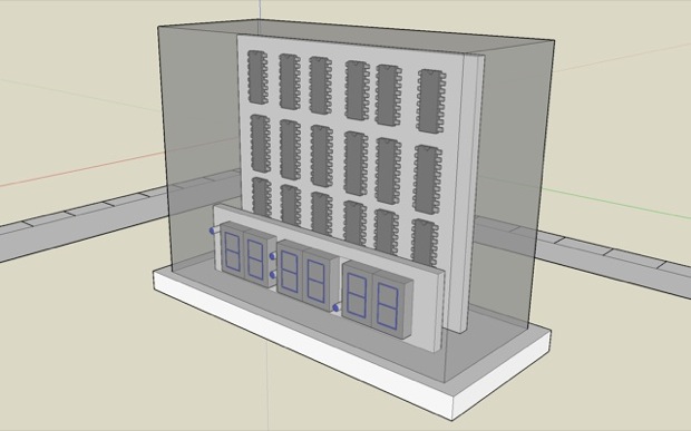
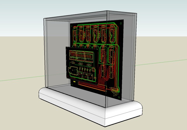
Here’s a quick mock-up of what I’m going for....
The Design
I used the free software provided by expresspcb.com. I had to run it in Fusion, sine they don’t have a native Mac application. I designed the clock schematic using a modular approach. There are three boards: the clock main board, the set/run/power board, and one for the display.
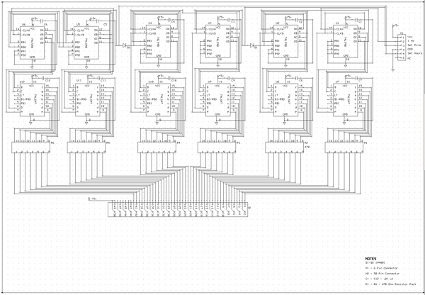
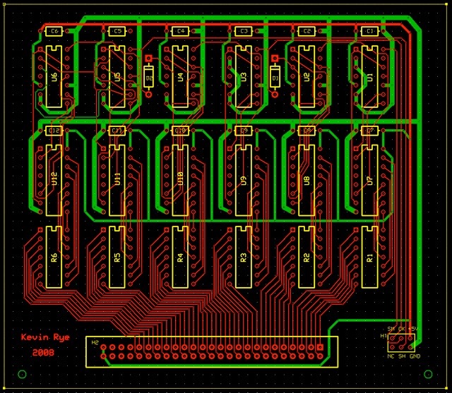
The following schematic shows the clock main board. Connectors are provided that will connect the main board to the clock input, power, and display.
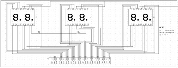
This is the clock display schematic.
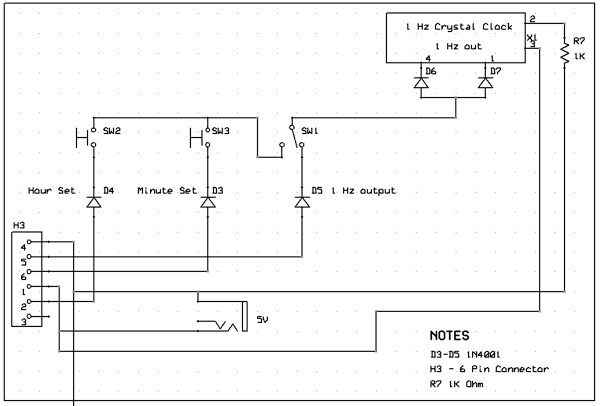
This is the power/set/run circuit. It provides the 1 Hz input to the clock, as well as a fast and slow signal for time setting.
I built prototypes to test the schematics for the hours and minutes sections before proceeding with the board design.
Using the above schematics, I designed the following 2-layer boards:
The Main Board
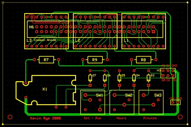
The following board is the set/run and display board. I tried to keep this one small since expresspcb.com will make you 3 “mini-boards” for only $51 ($60.85 with S/H) if you can squeeze it into 2.5” x 3.8”. This way I get 3 for future projects.
The Display Board
The Oscillator
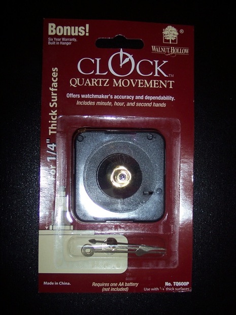
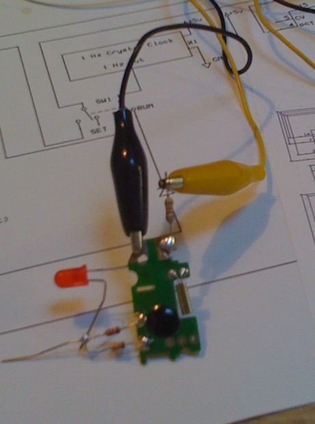
The last two clocks that I built used the 60 Hz line frequency from the wall outlet as a time base. I used 7490s to divide the signal down to 1 and 6 Hz. The 6Hz was used for the fast time setting. This time around I do not want to rely on the 60Hz. I want to be able to use a power supply like that from an iPod. So the power connector on the clock will actually be a USB socket. For the 1Hz time base, I am going to use the clock oscillator circuit that comes inside one of those cheap $6 hobby clocks. It’s cheap, they keep pretty good time, and I don’t have to make one.
$6 at the local craft store....and an excellent source of a 1Hz time base.
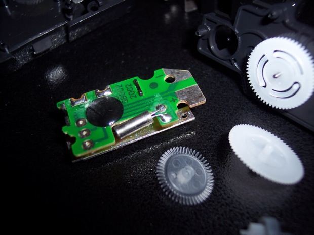
I hacked the oscillator board to run at 1 Hz instead of the default 2 Hz. I also added a 1K resistor so that I can run it off 5 Volts.
It totally works.
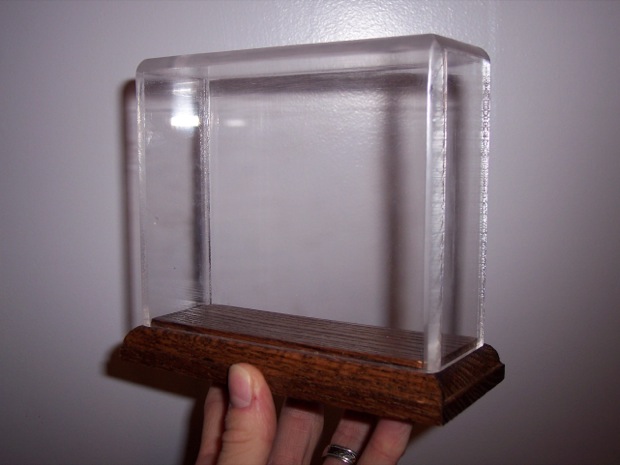
The Enclosure
I had a custom enclosure made for $20. It is made from 1/8” acrylic. It took almost 2 months to get here!
It will look something like this once complete:
The Boards
I ordered the boards from expresspcb.com. They arrived in 2 days. Not bad at all. They look awesome.
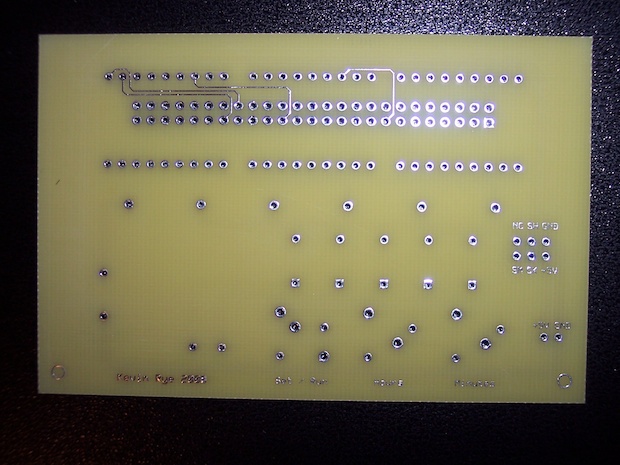
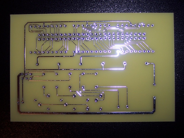
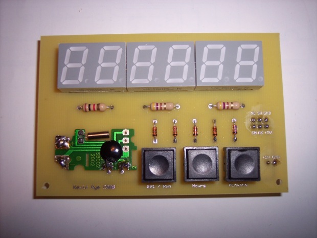
This is the front of the set/run/display board:
...and the back:
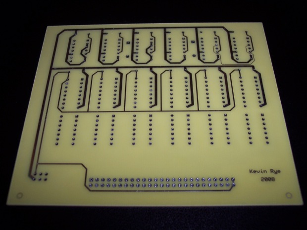
The main board is a bit bigger and does not qualify for “mini board” service. I used the “standard service “ for these. Green boards with silk screens would have been awesome, but that service is just way too expensive. I had two boards made for $93.92 with S/H. (There is a minimum of 2 for any order.)
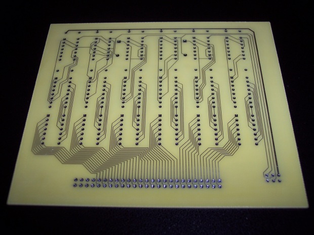
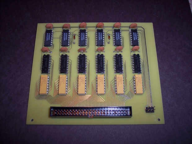
This is the front of the main board:
…and the back:
After you do the math, one clock can be made for $67.24. That combined with the $20 enclosure and a good $30 in parts, and I’m looking at a $120 clock!
Assembly
I started with the main board:
Followed by the display board:
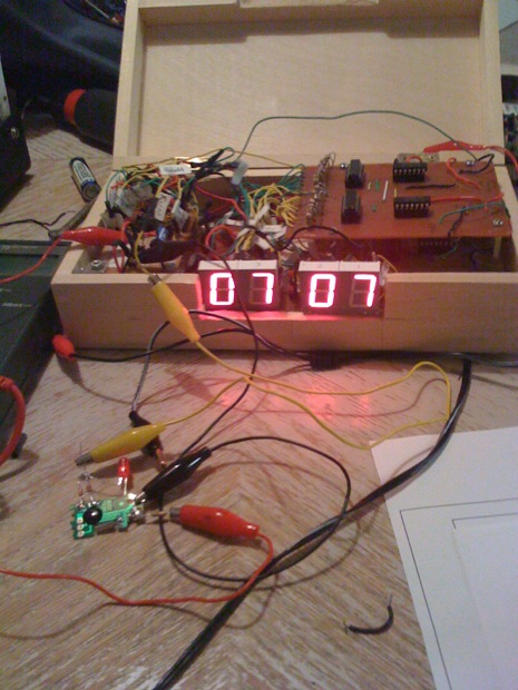
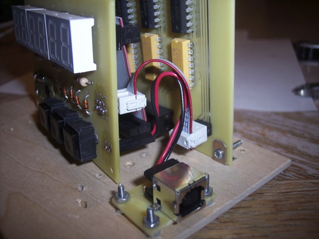
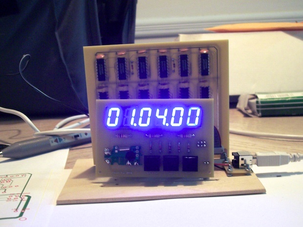
To test things out, I connected everything together on a board. The clock gets its power for a USB 5V adapter. In the finally version, the USB port will be on the back.