Back in the early 2000s, I got it into my head to build a nixie clock. The original plan was to build it using 7490 decade counters, but then I discovered microcontrollers.
I really wanted to make a clock that ran off one chip. This was, however, way before the likes of Arduino and anything open-source. From what I could gather, you pretty much had to build your own chip burner. You could go with something off-the-shelf from the likes of Microchip, but they were very expensive. Code examples, as well as tutorials weren't readily available, and software was limited. The whole thing seemed very daunting.
Needless to say,
I stuck with the 7490s.
I did however, pick up some nixie tubes and a VFD display just so I'd have them. I really jumped the gun on those. I bought them on a whim a little before I discovered how hard it was going to be. I got them off eBay, and they were very cheap. I think the VFD display was something like $3 bucks. So having it collect dust in a box wasn't a total loss.
I've since
built a nixie clock and subsequently discovered that those nixie tubes that I held on to for well over a decade were actually no good. Will this vacuum fluorescent display be any better? Can you imagine if I've been holding on to this display all these years to finally discover that it doesn't even work!
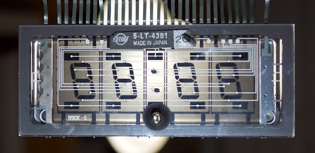
It's a FUTABA 5LT43.

The hard part with some of these old obscure displays is figuring out the pinouts, due to a lack of documentation.
Believe it or not, but the pinouts are actually on the back. Each little dot lines up with a segment. The lines show you how the segments are connected together and what pins they go to. You can also physically see the grids and what pins they correspond to.
If you do a search online for "FUTABA 5LT43", it’ll come up empty. This display is so old, there's just nothing out there.
Luckily, when I purchased it all those years ago, it actually came with a datasheet. This image isn't hard to read because I've scanned it in and shrunk it down. It really is that hard to read. It's a photo copy of a photo copy of a photo copy, etc.
I was, however, able to make out that the filaments need about 30V and the anodes need about 3V.
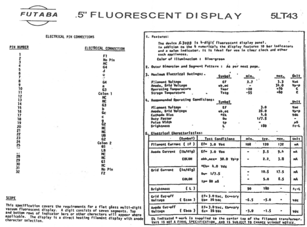
Back in the day, I took one look at that and was like, "Where am I going to get 30 volts from? And it says ‘30Vp-p’, isn't that peak-to-peak? As in AC? Where am I going to get 30VAC from?” I was used to running all my simple little projects off a 9V battery, and maybe if there was some TTL stuff, I'd use a 7805 to knock it down to 5V.
Even with this display, it seemed I was in over my head.
Since I recently "rediscovered" this display within one of my parts drawers, I re-reviewed the datasheet again to familiarize myself with the particulars.
Looking at it again, the datasheet states that it takes a max of 30V, with a
recommended value of 26V. There actually is no minimum specified, but I bet close enough is good enough.
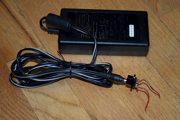
As luck would have it, I just happen to have a 24V adapter from an old scanner. I connected it to a barrel jack that had some breadboard-friendly leads on it.
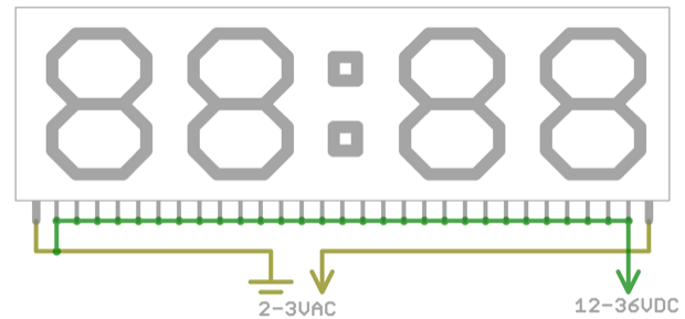
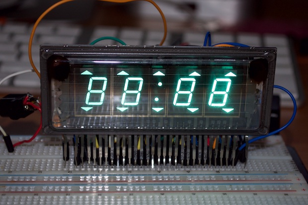
To power a VFD, you need to apply a good 12-36 volts to the anodes and 2-3 volts to the filaments. You're supposed to apply AC to the filaments, since DC will make the side of the display that's grounded a little brighter, due to the voltage drop. For testing purposes, I'm sure DC will be fine.
As you can see here, the filament on the right is connected to ground as the segment on the far right is much brighter than the rest. But anyway, holy cow! I got this thing powered! And it works!
With the display finally powered, I was able to go through each pin and verify it against the datasheet. There are several pins that do not have a connection. The curious thing I discovered is that the display is actually upside down from what I had imagined. As you see it plugged into my breadboard, it’s actually upside down. The pins are supposed to come out the top. If I had designed the PCB from what I had assumed, I’d be in for a big surprise!
With a little research, I discovered that I can drive this entire display from a single chip: the MAX6921. As far as chip prices go, they're sort of expensive at $6.61 a piece. So I think I’ll just pick up 2 for now. One to prototype with and one for the final assembly.
This has to be the most finely-pitched chip I’ve ever seen!
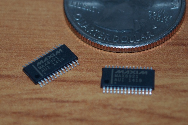
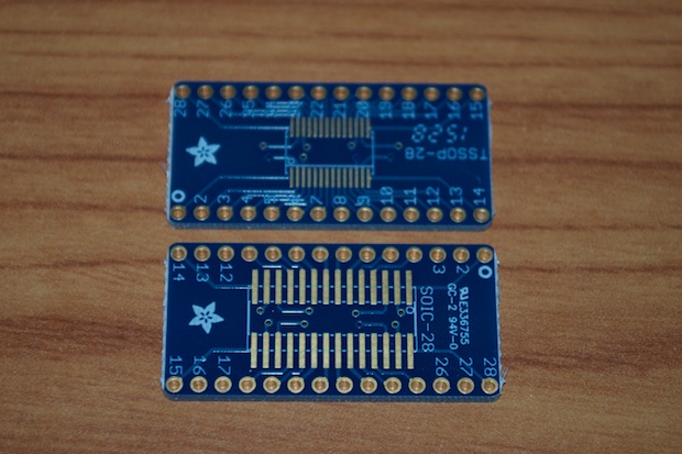
Since the MAX6921 is only available in a SMD package, I had to pick up some SMD to DIP adapters so that I can pop one on my breadboard.
Although the 24V power adapter that I have came in handy for testing the display, it's not exactly ideal for the final clock. I mean, the thing is huge.
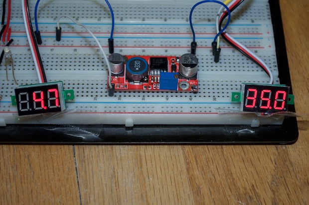
I decided to go with some XL6009 boost converters. I picked up two from eBay for $8 bucks.
These things are great. They have an input voltage range of 3V - 32V and an output voltage range of 5V - 35V with an efficiency up to 94%.
With these, I can power a vacuum fluorescent display off a USB port.
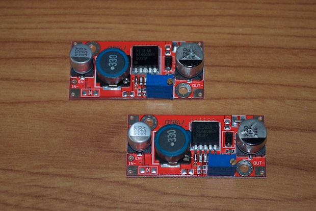
I did a simple power-on test just to make sure they worked. I connected ~5V to the input and monitored the output as I adjusted the trim pot. It maxed out at 35.0 volts. Awesome.
 See this project from start to finish:
I Finally Figured Out This Vacuum Fluorescent Display
VFD Clock - Part I VFD Clock - Part II VFD Clock - Part III VFD Clock - Part IV VFD Clock - Part V VFD Clock - Part VI Clock Button Panels
