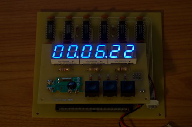
I made a really nice looking clock
back in 2008 using nothing but 7490 TTL Decade Counters. Despite the fact that it came out really nice, it never really worked right. Needless to say, I never finished it. (As far as putting it in an enclosure.)
In my old house, our mains was very noisy. The
first clock I made was very jumpy due to the lack of the numerous filter caps it probably needed. When It came time to make a newer/smaller clock, I figured the solution was to ditch the noisy 60Hz line frequency and go with a clean/stable 1Hz crystal.
I still put caps between Vcc and GND on every chip. Luckily, it doesn't bounce. The problem isn’t a noisy 60Hz signal. It’s the cheap 1Hz RTC I'm using. It intermittently runs fast, like 2 Hz. The 32K crystal it uses must be a real junker, or it’s damaged.
Another problem with the clock, and I don't know if it has anything to do with the cheap crystal, but half the time I can't set the minutes or hours. The switches are basically just a steering circuit for guiding the 1Hz signal into the seconds/minutes/hours segments. When in “run” mode, the signal reaches the seconds portion without a problem. Once I put the clock in “set” mode, the signal doesn’t pass through the switches to the minutes and hours segments. The signal just dies. The 7490s don’t count anything. Maybe I need to debounce the switches with some resistors? Maybe it's all the .7V drops across the diodes. I’ll have to play around with it and see. Maybe the switches are junk too?
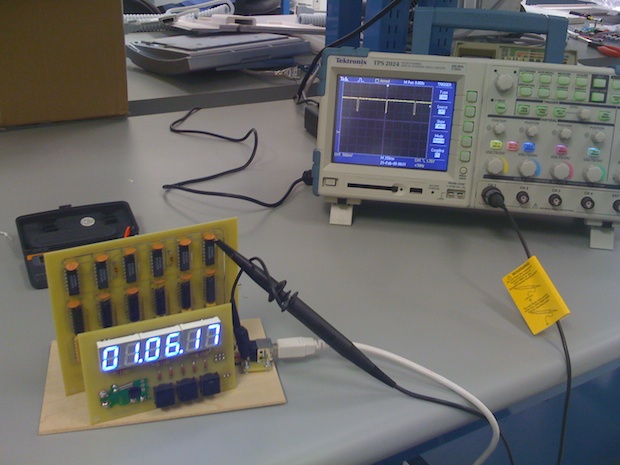
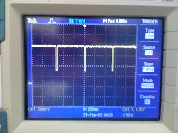
Years ago I hooked the clock up to a scope to check out the signal. It wasn’t the pretty little square wave that I hoped it would be.
It's not a 50% duty cycle at all. The falling edge is so small that I think by the time it passes through the switch, the first 7490 in the minutes and hours sections just sees it as Vcc, and not a clock. So I definitely need a new RTC.
Another problem is that one of the segments on the minutes section stopped working.
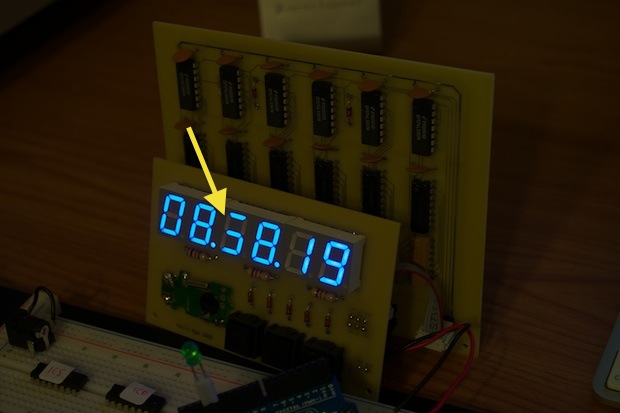
It used to work, so I though that maybe it was a defective display and that I’d have to unsolder it and put in a new one. Maybe the resistor on the mainboard went bad and it fried the LED? Although, resistors usually open, not short. I don’t remember one segment being brighter than the others. If I was running 5V through that LED, it would probably glow anything but blue. So I probably would have seen it coming.
I checked all the connections on the 50-pin connector and lo and behold…..it’s a dry joint! There’s hardly any solder on there at all. It’s amazing that it worked at all.
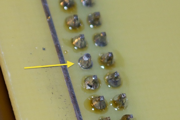
An easy fix. Thankfully, I didn’t have to unsolder all 18 pins and order a new 7-segment display. Those things were $7 a piece! After a touch of solder, I was back in business.
Since this thing’s been in a box for the past 4 years, it’s time to jog my memory on just how bad it keeps time. I powered the clock off my breadboard and let it run as-is for a day and a half.
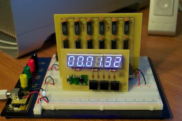
I meant to write down the actual start and stop times, but they weren’t even close, so I didn’t bother. It’s way off. It’s hardly a clock at all, more of a random number generator.
Time to try a better RTC. I unsoldered the cheap RTC and connected my
DS1307 breakout board to the clock. I connected the DS1307 to my Arduino and enabled the square wave pin to output a 1Hz signal.
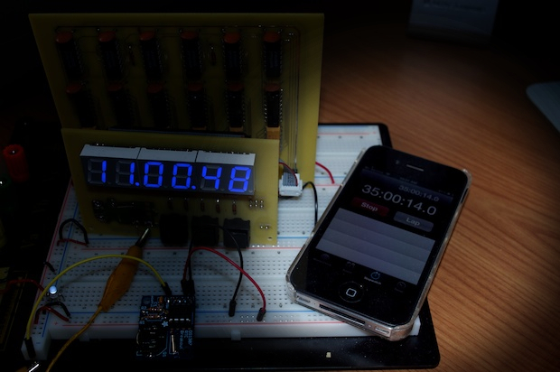
It's a little better, but it still gains time. I ran it for a day and a half and it was already 34 seconds fast. At that rate, the clock will be off by 17 minutes a month. That’s not much of a clock at all.
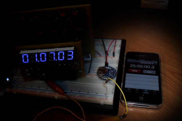
With that, I connected my
DS3231 breakout board to the clock to try that. Again, enabling the square wave pin to output a 1Hz signal. The DS3231 is a very stable clock. It has an internal, temperature compensated crystal inside. The disadvantage to most Real Time Clocks is that the crystal is external to the RTC. The clock will run fast or slow depending on the capacitance of the crystal in use. To make matters worse, that’s effected by temperature.
The DS3231 is supposed to be immune to those temperature problems. I let it run for another day. When I started the timer, my clock was already at 00:02:02. Judging by the timer on my iPhone, it’s only off by 1 second. I can live with that. It might actually be less than a second since I can’t see milliseconds on my clock. The accuracy of this test is a function of me being able to press the start button on my iPhone the instant I apply power to the breadboard. So it’s probably +/- 1 second.
It looks like the DS3231
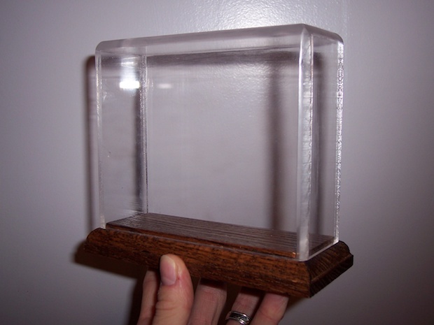
wins again. I'll have to design a new board for the display or find a way to hack it in. I’m determined to get this clock running right so I can put it on display. After all, it would be a shame to not get to use the custom acrylic enclosure I had made for it. Since the enclosure is transparent, whatever I do to fix it has to look really nice.
 See this project from start to finish: Digital Clock 3.0
 Fixing the 7490 Clock
Fixing the 7490 Clock, Part II Fixing the 7490 Clock, Part III
