I admit it: I'm a total geek. I love electronics, programming, 3D printing, 3D art, and vintage Apple hardware. I'm always juggling half a dozen projects. I also enjoy documenting it all: my successes, my failures, my experiences... and everything geeky along the way.
Fixing the 7490 Clock, Part II | Kevin Rye.net - Main
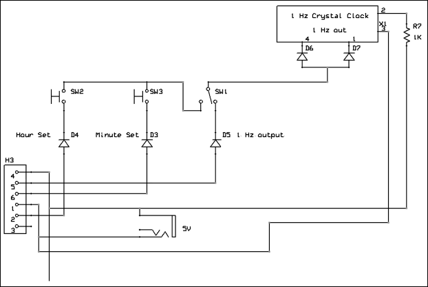
I used a cheap crystal and a crude setting circuit to set and run the clock. The crystal module put out a 1 Hz signal that, through a series of buttons, it would steer through to the seconds, minutes, and hours section of the clock.
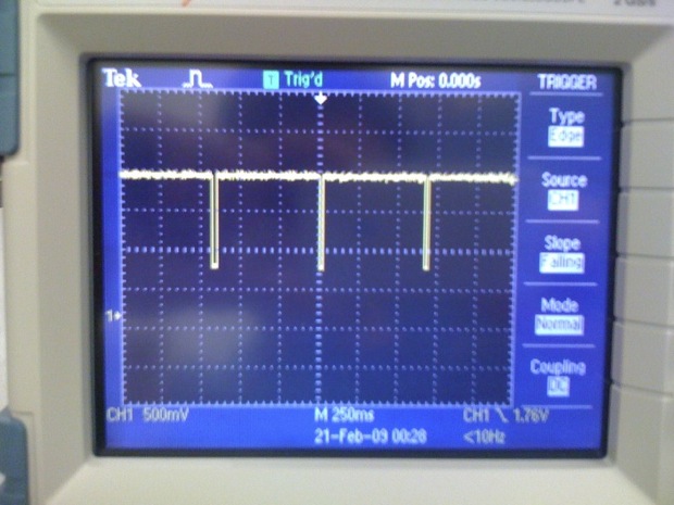
The problem was that the signal that the crystal module put out was pretty lousy. And those .7V drops across the diodes lead to some low-voltage signals.
The seconds section, more often than not, would run fast. After a day, the clock would run several hours fast.
When I’d redirect the 1Hz signal to the hours and minutes sections, it would appear as Vcc and not as a square wave. The input pins on the 7490s would be pulled high and they wouldn’t count.
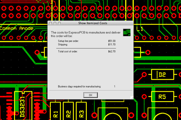
The main reason I held off on fixing it at the time was that the entire display board needed to be redesigned to use a better crystal. I had the boards made by ExpressPCB. They offer a MiniBoard service. They’ll make you three 2.5" x 3.8" prototype boards and ship them out in a day for $51. They are prototype boards, so they don’t have solder masks or silk screens. That seemed like a pretty good deal since most fab houses charged a lot more, included set up fees, and had much larger minimum quantities. Another benefit was that ExpressPCB supplied you with free software to design the circuit and the PCB. After you’ve completed your design, you submit you order directly from within the program. Back in 2008, I didn’t know anything about EAGLE or having custom PCBs made, so ExpressPCB seemed to be an easy all-in-one solution.
The first boards that I had made didn’t work. I can’t remember exactly what the problem was, but I think I screwed up the pinouts on the LEDs. I fixed that and submitted another order.
That’s why I held off on yet another redesign. I was already in the hole for $124 bucks. ($51 x 2 plus $11 x 2 in shipping.) Not to mention the $100+ that I spent on having the mainboard made. (Two boards at $50 each, plus shipping.) Back in 2008, I knew nothing about RTC chips or microcontrollers. I didn’t know the first thing about how to improve on the design. I didn’t want to order another board fearing that it wouldn’t work. I knew the crystal was the problem. I just didn’t know how to make it better. I couldn’t bear the thought of a $300 clock that didn’t work. Even now, $300 is still a lot of money, but that’s water under the bridge. It’s not about the money any more, it’s about getting this clock to work, into the custom acrylic enclosure I had made for it, and put on display.
Six months ago, I decided to learn how to program and develop with the Arduino platform. I’ve been working with the ATmega328, the ATtiny85, and the DS3231 RTC. I’ve been using EAGLE, and had a bunch of boards made by OSH Park. I’ve made all kinds of cool stuff, and I think I’ve gotten pretty good at it. I figured it was time to revisit the 7490 clock and see if I could use a microcontroller to improve the design.
For a minute I thought about redesigning the entire clock in EAGLE, but that would be wasteful. The whole point in redesigning the display board is so that the $50 mainboard won’t be wasted. There’s nothing wrong with it, so it doesn’t make sense to have another one made. Sure, it would be nice to make one in EAGLE and have it sent to OSH Park. It would look pretty cool with a solder mask and a silkscreen. The PCB would take up the entire allowable area of the free version of EAGLE and would cost about $45 to have 3 boards made by OSH Park. But what would I do with the old one? I’d hate to throw it out.
The only option is to design another display board and have it made by ExpressPCB. That way, the mainboard and the display boards both match. Luckily, ExpressPCB still offers their MiniBoard service for $51.
Unfortunately, I've since switched to the Mac and ExpressPCB does not offer a Mac version of their software. The stars must have been aligned, because Stacksocial just offered a pretty sweet “Name Your Own Price” software bundle. The price starts out low and slowly climbs as more people buy it. I guess the idea is to force people to jump on it before the price goes up. I bought in pretty early, so I got it for $8 bucks. Not bad for $400 dollars worth of stuff.
But what does any of that have to do with redesigning my 7490 clock? Well, that $8 software bundle just happened to include CrossOver 12 by CodeWeavers. CrossOver lets you run Windows programs on your Mac. It’s not a Windows emulator. It uses an implementation of WINE (Wine is Not and Emulator) to provide a compatibility layer for UNIX-based Operating Systems.
From Wikipedia:
WINE is a compatibility layer. It duplicates functions of Windows by providing alternative implementations of the DLLs that Windows programs call, and a process to substitute the Windows NT kernel. This method of duplication differs from other methods that might also be considered emulation, where Windows programs run in a virtual machine.
CrossOver 12 is usually $59.95, and is not something that I would have otherwise purchased on its own. In most cases, you can always find a Mac alternative for whatever PC software you use. I’ve never had a problem finding an app for what I need to do. But for some custom, propriety app like that of ExpressPCB’s software, you’re stuck using their PC version. My kids have a PC, but I’m not about to sit in their bedroom on a small 20” LCD to do it.
CrossOver to the rescue!
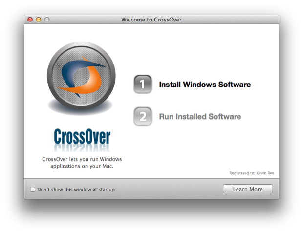
After running the installer, you’re presented with the following menu:
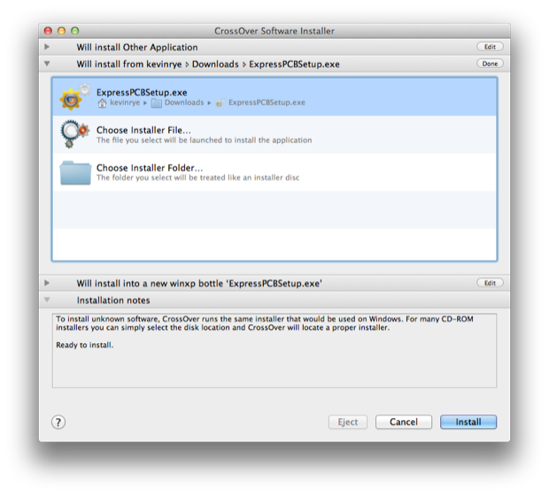
You just have to select “Install Windows Software” and browse to the Windows executable you want to install.
WINE creates what they call ‘bottles”. (See what they did there?) They’re like containers that provide all the necessary files and resources that a Windows program needs to run, access the internet, or talk to your peripherals. (USB, etc.) Once CrossOver has created a “bottle” for your app, it installs the Windows program into that “bottle”. After a second or two, the installer will pop up and run just like it would in Windows.
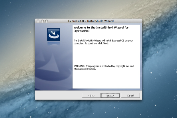
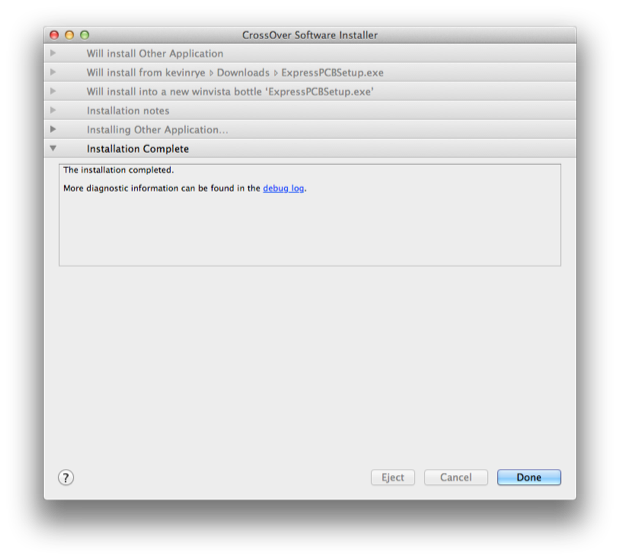
You step through the installer just like you would in Windows. When it’s finished installing, CrossOver will tell you that the installation was complete.
You can then click “Done” and the app will launch.
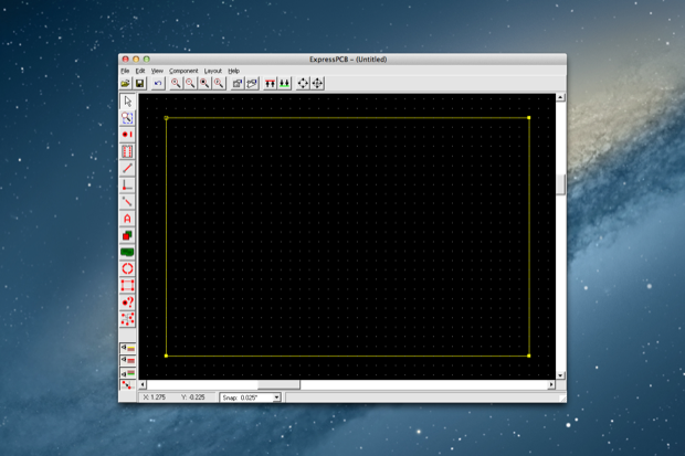
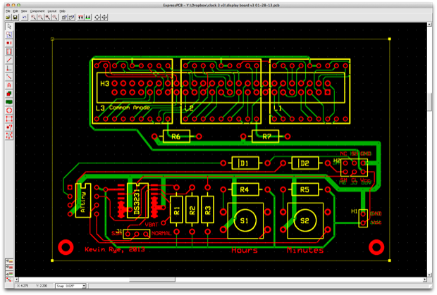
Boom! ExpressPCB running on my Mac!
I then opened my old design file from 2008. CrossOver provides full access to the Finder just like a native Mac app. You can navigate to your files just like you’d be able to do in any other app. It’s not like an emulator where the app can only “see” what’s in the emulator. Remember, Wine Is Not an Emulator!
I do admit, there is a hit in performance. Movements are slow and it does take a second or two for the screen to update. I don’t know if it’s just this program or if all Windows programs will run this slow. I’m willing to put up with it since I’m in a pinch. I know CrossOver has made tweaks for some of the more popular Windows software so that they run a little better, but I guess some random Windows program like ExpressPCB just runs as-is with general settings.
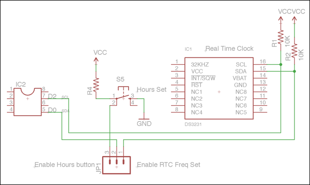
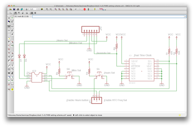
In any case, it’s bearable and I should be able to do what I need to do. I jumped into EAGLE and started to design a new board. My previous testing showed that the DS3231 is the clear winner when it comes to an accurate 1Hz signal. But how do I drive it? Using an ATmega328 would be total overkill. An ATtiny? I don’t know if it has enough I/O pins to pull it off. The reset pin (D5) is out, so I’m left with D0-D4. I need two pins to talk to the DS3231. I need two pins for the hours and minutes set buttons. I then need 2 pins to output a signal to the hours and minutes sections. Hum. Looks like I’m a pin short!
The solution? I’ll use a jumper to toggle a pin function between talking to the DS3231 and setting the hours.
With that sorted out, I moved forward with the rest of the design.
On the DS3231, the INT/SQW pin can serve as either an interrupt for alarm functions, or output a square wave at 1Hz, 1KHz, 4KHz, or 8KHz. Since the DS3231 does not have any onboard storage, there’s no way to save that setting. I’ll have to “tell” the DS3231 to run at 1Hz at startup. You can retain the setting during a power outage by providing a battery backup, but the DS3231 still has to be configured at some point.
The ATtiny does have SCL and an SDA functions on pins 5 and 7, so it can talk to the DS3231, but it does not have a serial port. After importing the TinyWired library, I was able to emulate a serial port in software and have the ATtiny talk to the DS3231 over the SCL and SDA lines. At startup, the ATtiny will tell the DS3231 to output a 1Hz square wave.
Here’s the code to set the 1Hz square wave on the DS3231:
Once the clock powers up and the DS3231 is configured to output a square wave, I can throw the jumper to connect to hours button to pin 5. I’ll only have to throw the jumper if I lose power.
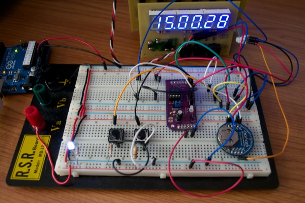
I prototyped the whole thing on my breadboard and it worked like a charm. I ran it for 24 hours and it didn’t lose a single second.
The 1Hz output from the DS3231 goes directly to the clock mainboard and is completely independent of the ATtiny. In other words, there’s no way to stop the seconds while setting the clock. No big deal. On any other clock where the seconds aren’t displayed, you don’t really know what the seconds are doing anyway. I’m no longer redirecting the 1Hz signal from the seconds section to the minutes and hours sections. I’m using the ATtiny to output a signal for those.
The ATtiny monitors the hours and minutes set buttons on D0 and D1. If the hours button goes HIGH, it’ll output a signal on D3. If the minutes button goes HIGH, it’ll output a signal on D4.
You can single-click the buttons and increment the minutes and hours one at a time. Or, if you press and hold the buttons, after a few seconds the minutes or hours will increment faster. Holding the minutes a little longer still, and it will increment really fast.
I put a counter in the code to keep track of how long you’ve held down the buttons. The output will then change based on the count.
 //set mins button pressed
  if (digitalRead(minSetButton)== 0) {

    minCount++;
    //slow set
    if (minCount < 3) {
      digitalWrite(minOut, HIGH);
      delay(100);
      digitalWrite(minOut, LOW);
      delay(500);
    }

    //fast set after 3 seconds
    if (minCount >= 3 && minCount <= 20) {
      //fast set
      digitalWrite(minOut, HIGH);
      delay(100);
      digitalWrite(minOut, LOW);
      delay(100);
    }

    //really fast set after 3 seconds
    if (minCount > 20) {
      //fast set
      digitalWrite(minOut, HIGH);
      delay(25);
      digitalWrite(minOut, LOW);
      delay(25);
    }
  }

//reset the counter when the button goes LOW
  if (digitalRead(minSetButton)== 1) {
    minCount = 0;
  }
The code for hours is the same, except for lacking the “really fast” portion.
Here’s a video illustrating the much-improved time setting scheme:
Pretty cool. That’s a major improvement from the old design. With the old design, simply steering a 1Hz single to the minutes portion of the clock made setting the clock a very time consuming process. If you were setting the minutes and you missed your mark, it would take a full 60 seconds to wrap back around and get back to where you started. If you goofed again, or messed up the hours, it meant setting the clock could take you several minutes. Torture! Setting a clock should be click, click, done.
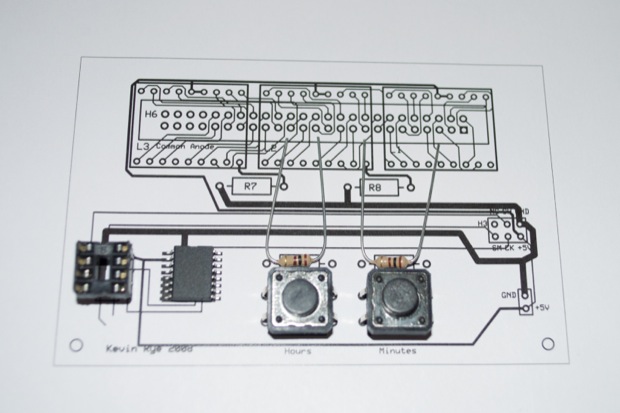
With the prototype nailed down, it was time to redo the PCB design. ExpressPCB doesn’t have a lot of pad designs for components. It has the basics: resistors, capacitors, DIPs, etc. When it comes to LEDs and switches, you’re on your own. I designed a pad for my switches and printed it out to make sure that everything lined up correctly.
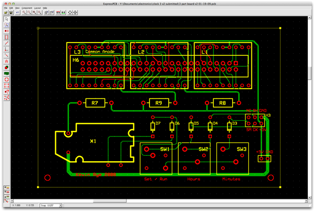
Good to go. I then populated the board with the rest of the components.
The top half of the board remains unchanged. There was nothing wrong with that, so it stayed the same. I just had to redo the bottom half of the board.
Once I was happy with the design, I submitted my order. Just like last time, I was given a price of 3 boards for $51, plus $11 for shipping.
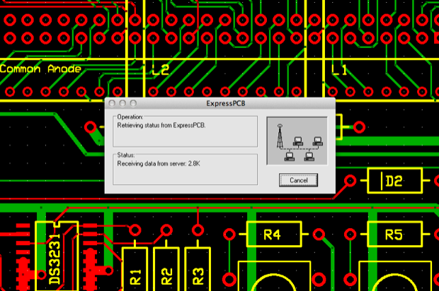
After punching in my address and payment info, my PCB was uploaded.
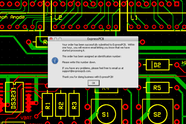
I then received an order confirmation.
Even with CrossOver, all the networking “stuff” works. I did have my fingers crossed. I was afraid that some aspect of the program wouldn’t be supported and the whole thing would crap out during the order submission. Or I’d press a button and it just wouldn’t do anything.
Lucky for me, the process was painless. I should have my boards early next week.
Woo hoo! I can’t believe after 5 years this clock will finally be complete! Yeah progress!