I admit it: I'm a total geek. I love electronics, programming, 3D printing, 3D art, and vintage Apple hardware. I'm always juggling half a dozen projects. I also enjoy documenting it all: my successes, my failures, my experiences... and everything geeky along the way.
GPS Clock Prototyping, Part III | Kevin Rye.net - Main
I decided to ditch the IR remote in my GPS clock in favor of buttons. Once I had all the IR code implemented, I realized that it just wasn’t the way to go. I really wasn’t happy with the performance. The Wire library and IR library kind of step on each other. I put in some tweaks in an attempt to mitigate things, but it’s wonky at best. The lackluster performance with the remote was also putting a damper on development. It made it really hard to troubleshoot my code. Half the time I couldn't tell if my code wasn’t working or if it was the remote that was acting up.
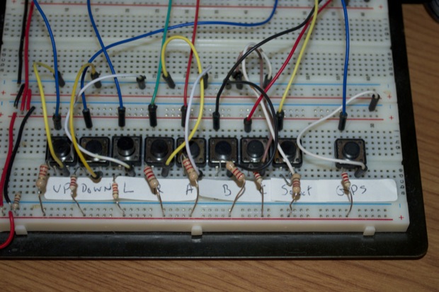
Instead of the IR remote, I’m basically going to include a keypad on the clock that pretty much mirrors the functionality of the remote. I have buttons for UP, DOWN, LEFT, RIGHT, SELECT, MAIN SCREEN, SETTINGS MENU, ALARM MENU, and GPS DATA.
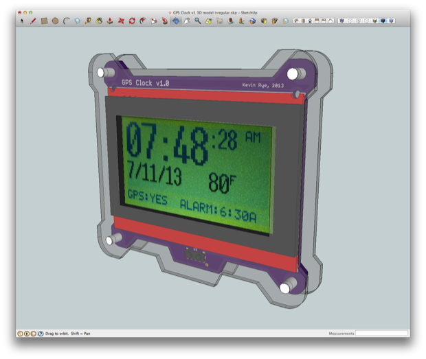
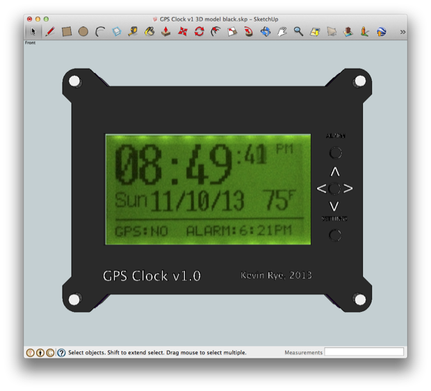
The original idea was to make the clock no larger than the display itself. Something like this:
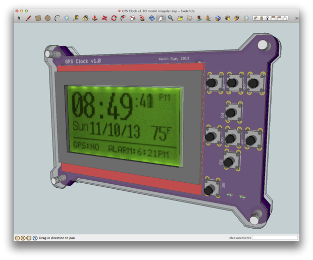
With the addition of the keypad, I’m going to have to extend the length of the clock. I’ll place the buttons on the right side of the display. I usually like to place the buttons under the display, but I think this will look cool.
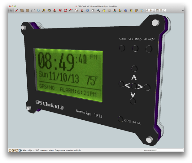
I also like to make the acrylic translucent in order to showcase the electronics, but since everything is going to be on the back, I might just make the front panel black and have the text engraved and filled.
With the buttons sorted out, I could push onwards with the audio stuff. I want to add an alarm feature to the clock as well as a “chime on the hour” function.
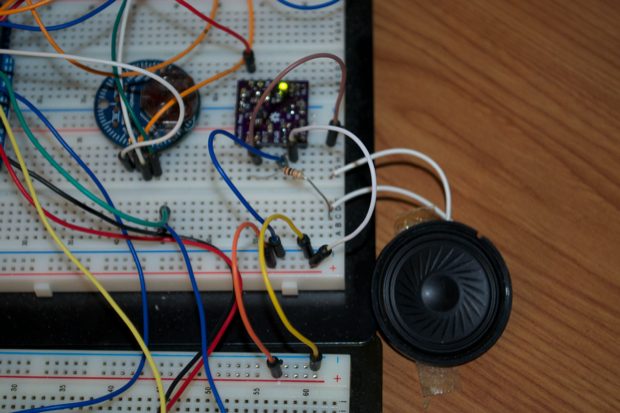
For the audio, I added my mini audio amplifier and a speaker. To keep the clock as small as possible, I’m going to incorporate the audio amplifier into the mainboard as opposed to adding it as a daughter board like I’ve done in the past.
In order to chime on the hour, I just have to trigger an audio tone when the minutes are equal to zero. I haven’t settled on a final audio tone, but to test that it works, I’m just playing a simple tri-tone.
  if (chimeOnHour == true) {
    if((mmRTC == 0) & (ssRTC < 01)){

      Serial.println("chime");
      // play a note on pin 4 for 10 ms:
      tone(4, 2794, 10);
      delay(400);
    }
  }
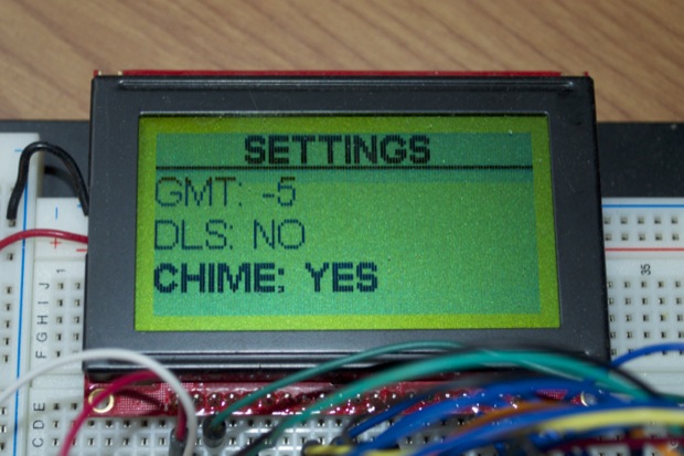
The “chimeOnHour” boolean is set via the Settings Menu.
Here’s “chime on the hour” in action. I didn’t feel like waiting an hour for it to go off, so for the video, I altered the code so that it goes off when the minute hits “9”. You get the idea.
As far as the alarm, I could have linked to the Time and the Alarm libraries, or used the alarm feature of the DS3231, but I wanted to keep it simple. Triggering an alarm is easy. I just save my alarm time to a variable and then compare it to the current time. If they’re the same, I alarm.
OK, maybe it’s not that simple, but that’s the basic idea. There’s a lot more to it than that. For example, I only want to alarm when I’m in normal mode. I only want to alarm for 20 seconds. I also want to be able to mute the alarm. I also want the amplifier to shut down when it’s not in use.
That was all solved with a few booleans and a bunch of “if” statements.
//disable amplifier if alarm is not sounding
  if (alarmIsSounding == false) {
    digitalWrite(amplifierShutdown, LOW); //turn amp off
  }
  else {
    digitalWrite(amplifierShutdown, HIGH); //turn amp on
  }

//re-enable alarm after 20 seconds for next alarm iteration if it was
//previously silenced
if ((alarmWasSilenced == true) & (ssRTC > 20)) {
  alarmWasSilenced = false;
}

  //alarm only when in normal mode and when alarm is active
  //alarm for 20 seconds
  if ((alarmIsActive == true) & (enterNormalMode == true) && (ssRTC < 20)) {

    if (alarmWasSilenced == false) {

      if((alarmHours == hhRTC) & (alarmMinutes == mmRTC)) {

        alarmIsSounding = true;

        Serial.println("alarm active");
        // play a note on pin 4 for 10 ms:
        tone(4, 2794, 10);
        delay(200);
      }
    }
  } else {
    alarmIsSounding = false;
  }

  //disable amp if 'select' button is pressed while the alarm is sounding
  if ((digitalRead(selectButton) == LOW) & (alarmIsSounding == true)) {

    alarmWasSilenced = true;
    alarmIsSounding = false;

  }
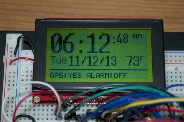
Here’s the alarm in action. You’ll see in the video that I press the ALARM button to bring up the Alarm Menu. I then press the navigation arrows to navigate through the menu and set the time to 6:21 PM. I then press the MAIN button to go back to the main screen. The new alarm time is posted to the bottom-right hand side of the display. Then, when the clock hits 6:21, the alarm goes off.
I silenced it in the video after a few seconds, but the alarm does persist for 20 seconds before stopping and shutting down the amplifier. The code then resets so that it’ll go off the next time the alarm hits.
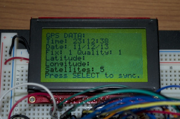
I also thought it would be useful to put in a GPS data menu; in case I want to know why my clock isn’t syncing or something. I’d maybe like to look at the raw data coming from the GPS module. Maybe I’ll want to see how many satellites are connected, as well as longitude and latitude, etc. I was thinking of putting an LED on the front of the clock to indicate the fix status, but that seems redundant considering the fix status is already on the main screen. Besides, if I make the front of the clock black acrylic, I won’t be able to see any LEDs on the PCB.
Instead of the SYNC button forcing a manual sync, it now brings up a “GPS DATA” menu.
If I’m in the GPS DATA menu, pressing SELECT with force a re-sync. I only push the GPS data to the DS3231 RTC if I have a fix. If there is indeed a fix, it’ll also be indicated on the main screen as “GPS:YES”.
With all the settings in place and all the menus set up, it’s just a matter of saving everything. I want to be able to save the Time Zone, Daylight Savings, Chime on Hour, Alarm Time, and Alarm Status settings to the ATmega’s EEPROM. I then want to read it all back in at startup.
The ATmega’s EEPROM has a lifespan of 100,000 writes. I could save the settings once a day for 273 years. That sounds like a lot, but what if I messed something up and it saved it every minute? I’d burn the chip out in under 3 months. Also, if I wrote to the EEPROM every time a value was changed, going from GMT 0 to GMT -5 would use up 5 writes. Not to mention changing the alarm would burn though a ridiculous amount of writes. I basically only want to save a setting if the value has changed since the last save. So I’ll have to do a lot of comparing of values in order to limit the amount of writes I do to the EEPROM. In addition, I don’t want to do a brute-force “save all settings” either. There’s no sense in saving the GMT value if the only thing that changed was the chime on hour setting.
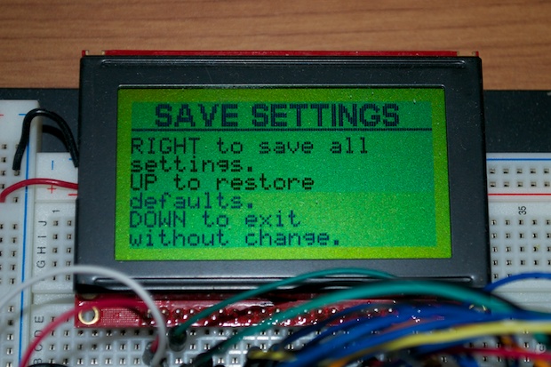
In order to save the settings, I’ll need a new menu. I updated the code so that if I’m at the main screen, pressing the SELECT button will bring up a SAVE SETTINGS menu.
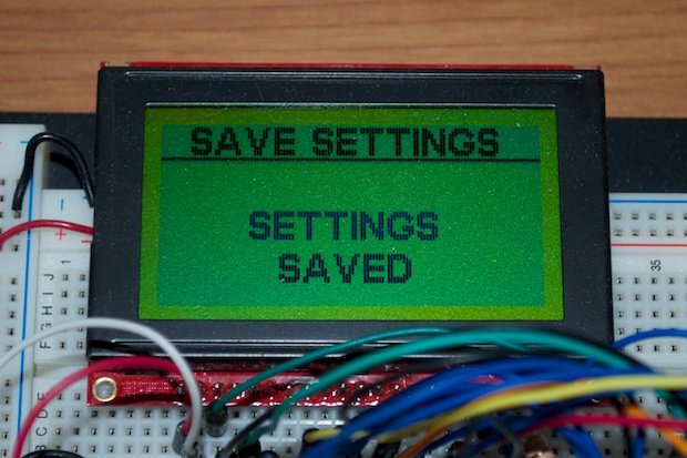
If I press the RIGHT button, I’ll "save all settings". (In reality, I only save the settings that have changed from the default, and only the values that have changed since the last save.) That will then give me a confirmation screen and then take me back to the main screen.
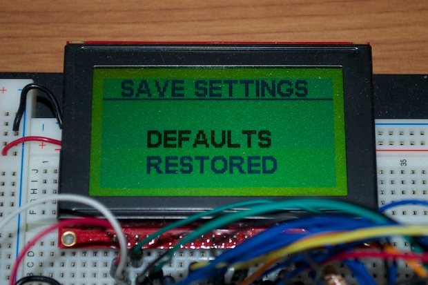
If I press the UP button, I’ll restore all the default settings. I don’t know if I’ll ever need to do that, but it’s a nice feature. Everything should have a “factory default” option. Again, I’ll be given a confirmation.
To exit without doing anything, I can just press the DOWN button.
I only planned on having three menu buttons: the ones for navigation, and the one for GPS. I need another button to enter the SAVE menu, but I really don’t want to add another button.
I might make both the GPS and SAVE Menus an option within the SETTINGS menu and ditch those two buttons altogether. I could also get rid of the MAIN button and just put an EXIT option in all the menus that could take me back to the main screen. I'll have to shrink my fonts, but it's doable.
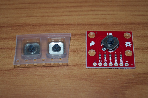
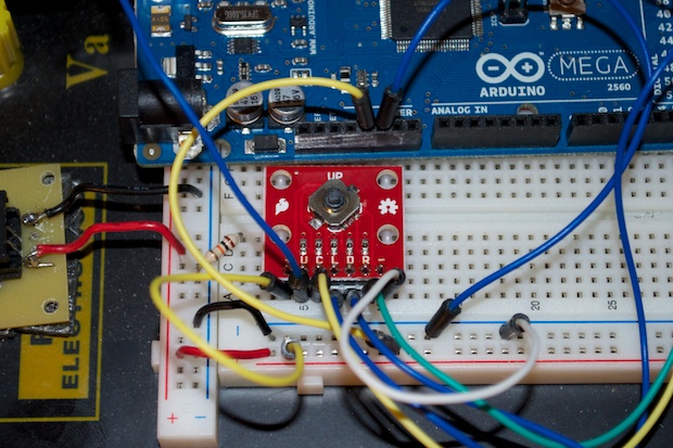
I wrestled with it a bit and came to the conclusion that I really don’t want to have 9 buttons on this clock. I hopped on SparkFun to see what my options were. I found this teeny-tiny 5-way switch that looked perfect. I ordered a few of them as well as a breakout board.
I soldered a header on to the breakout board and added it to my breadboard. I managed to eliminate 5 buttons by using this one switch!
I really like the way that this switch feels. It's solid. I feared that it would be a little rickety thing that was more of a gimmick than anything, but it's nice and tight and really responsive. I just wish that it came with a knob or something. I checked with SparkFun, but they don't provide anything. Judging by the amount of requests in the comments on their site, it looks like no one's found anything suitable for it either. I just might have to fashion something out of Sugru so that it can clear the clock's acrylic front panel.
By combining 5 buttons into one, I might be able to shave an inch off the clock. I'll jut need buttons for ALARM and SETTINGS menus.
Come to think of it, why don’t I just put everything in a menu and just use the 5-way switch for everything? I could bring up a "master" menu with the center select button. I could get to Alarms, Settings, GPS, and Save all with submenus. I could then put the 5-way switch on the bottom where the IR recover was going to go and make it even smaller!
I’ll have to chalk up some code and see if the menu structure is feasible.
Other than that, there’s just a few last-minute tweaks to do and I think it’s on to designing the PCB. I had started it months ago, but now it’s a complete do-over since I ditched the IR receiver and switched from an ATmega328 to an ATmega2560.