I got my
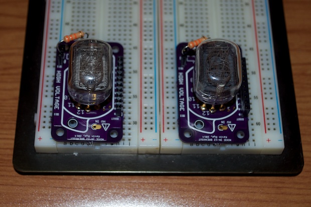
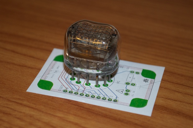
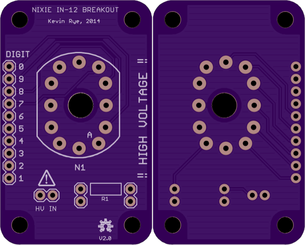
nixie breakout boards in the mail. One look at them and I knew right away there was a problem.

It’s pretty obvious from the silkscreen on the PCB that the IN-12 footprint is designed for an IN-12 socket. I thought that the nixie pins I ordered from eBay would also fit. Not so. These pins are tiny.
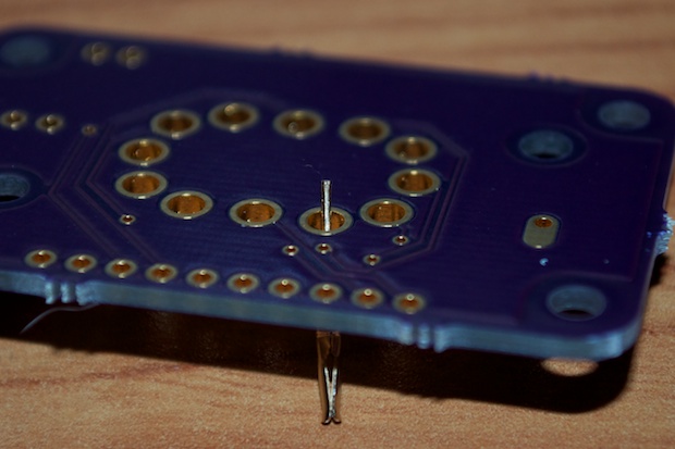
Once mounted, the nixie just doesn’t sit right. The amount of solder I’d need to use would end up making a big sloppy mess. I decided to ditch the pins and order some IN-12 sockets. I’d rather do it right than do it willy-nilly.
IN-12 sockets. I ordered 6 off eBay. Once again, they took a month to come from overseas. If I have to wait 3-4 weeks every time I need a nixie clock part, it’ll be months before my clock is complete.
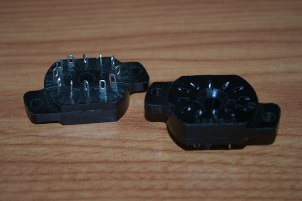
It’s really unfortunate that I had to wait a whole month to find out that the footprint on the PCB isn’t any good. The holes are a tad too small. Out of the 6 sockets, I only managed to find 2 that I was able to force into the PCB. Even still, they don’t go all the way in; it’s just enough to be able to solder the leads. Another problem is that once the socket is in the PCB, it’s even harder to insert the nixie. Of the 8 nixies I have, not a single one would go in the socket once I jammed it into the PCB.
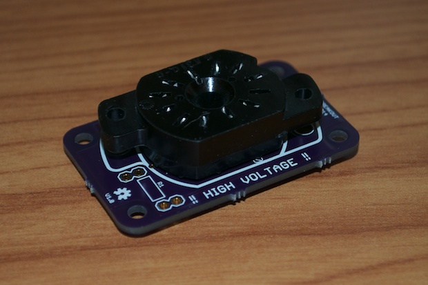
It looks like I’m going to have to stick with my original plan all along and just use the nixie pins. I’ll just have to cross my fingers and hope that it works.
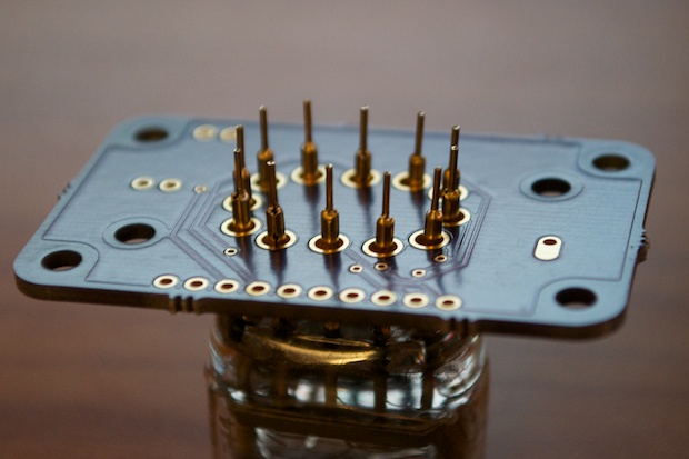
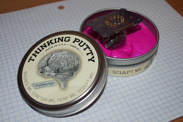
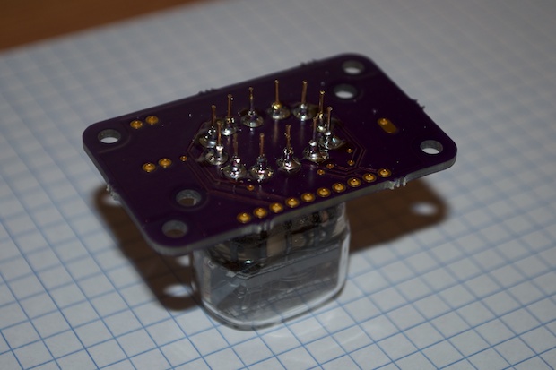
OK, so how do you keep the PCB steady when the nixie is rounded? I just used a little Thinking Putty. Literally.
That should do the trick. It really didn’t turn out as bad as I thought it would. I didn’t need to use as nearly as much solder as I originally thought. The nixies slide in and out of the pins without a problem. Again, it really stinks that I lost a month on this project because of a $1.25 nixie socket. I should have just used the pins a month ago.
After soldering the pins in, I trimmed the leads down a bit so it’ll sit flat on my breadboard.
I then soldered in the 10-pin header for the segments and some 2-pin headers for the resistors. I didn’t want to solder them directly to the PCB. This way I can experiment with various resistor values.
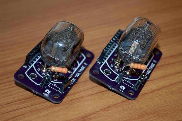
I then popped them in my breadboard.
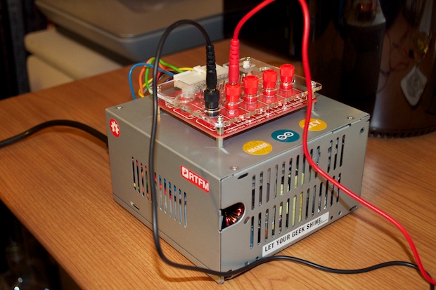
I connected my new
bench-top power supply to my breadboard and fired it up.
Immediately, I knew something was wrong. No digits light up. I wondered if it was just a bad nixie, so I tried another one. Same results. They both can’t be bad. I checked the pinouts again and realized that the numbers on the silkscreen for the pins are upside down! What?! I could have sworn I checked that.
I flipped the nixie around 180 degrees. Some of the digits light up now, but others don’t. In addition, the digits that light up aren’t the ones I’m expecting.
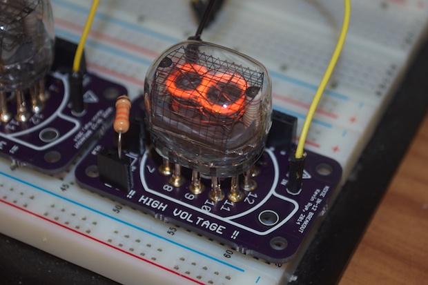
For example, when I ground pin 11, the nixie displays a “7” when I should be getting a “5”. What gives? As it turns out, not only are the pinouts on the silkscreen upside down, but they are the bottom view, not the top view. The whole thing is wrong. Who designed this thing?
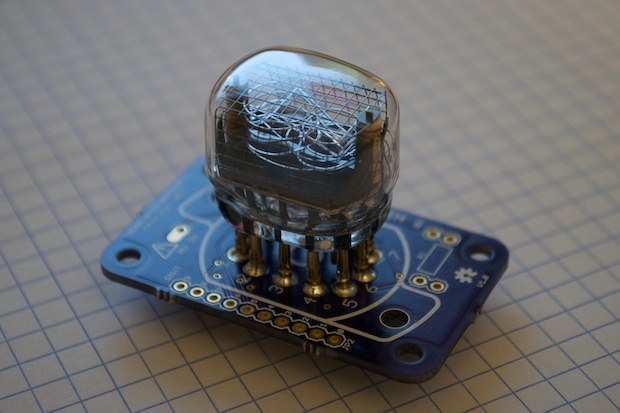
By touching a ground probe to each pin, I was able to figure out what is actually what. I found a new nixie footprint online that matches the pinout and redid my whole PCB. See, this is why we prototype! Imagine spending $50 bucks on a final design to find out that the pinouts are buggered!
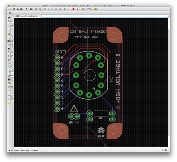
This definitely looks like a better fit. I’ll forgo the sockets on this one and just use pins.
Hopefully rev 2 doesn’t take 2 weeks to arrive.
Yet another delay in the nixie tube clock.
See this project from start to finish: Nixies! Got My Nixies Powered! IN-12 Nixie Breakout Board, Part 1
Flashing a Nixie with an Arduino IN-12 Nixie Breakout Board, Part 2 Driving a Nixie with a 74141 BCD Decoder More Nixie Tube Experiments Nixie Clock 5V / 12V Power Supply Nixie Clock PCBs / EAGLE Upgrade Nixie Clock Main Board PCB Build Nixie Clock Final Build, Part I Nixie Clock Final Build, Part II Nixie Clock Final Build, Part III Clock Button Panels
