When I had
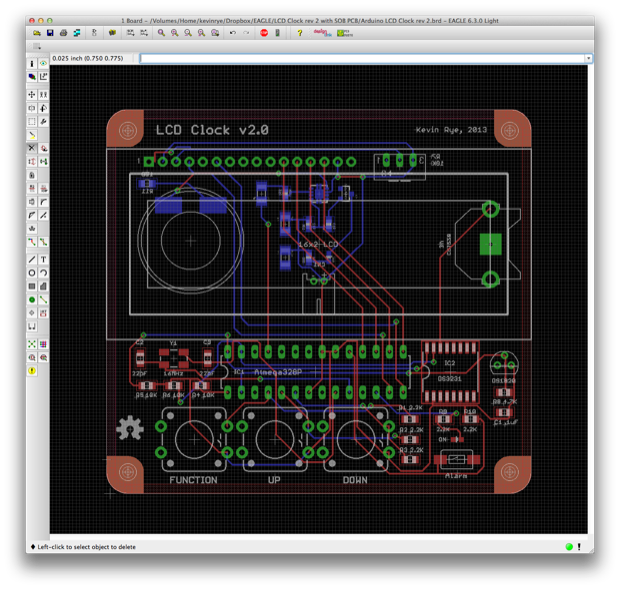
shelved this clock a year ago, I had gotten pretty far with the PCB. Although I still had some design decisions to make, as well as a ton of code to write, it was pretty much complete.
The layout of the PCB was pretty much the same between the two revs. I used SMD caps and resistors this time around, but I was still working with through-hole ATmegas. It was basically a nicer looking rev 1 with an alarm function.
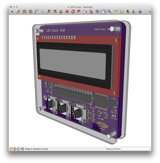
I had even gone as far as creating a 3D model.
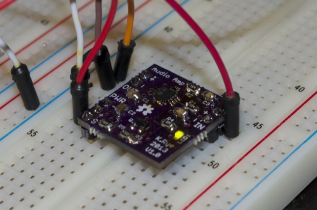
I even prototyped an
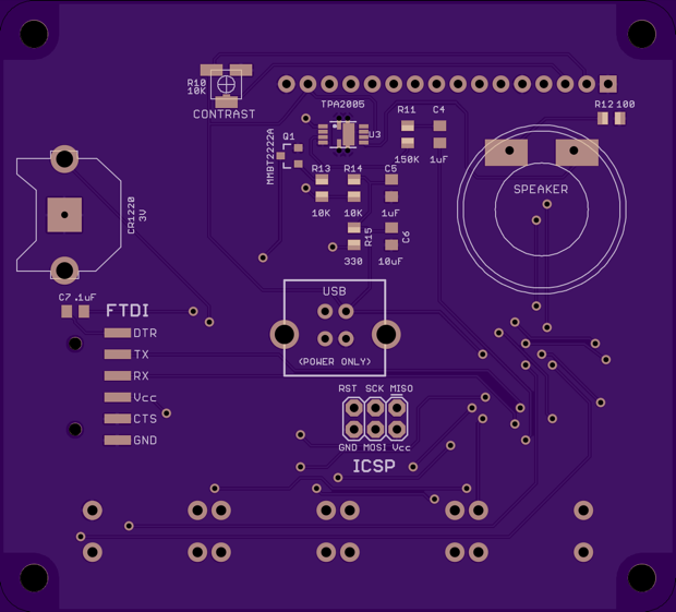
audio amplifier for the alarm function. I didn't want to spend $50 bucks on PCBs to find out the audio didn't work. I figured I'd start out small and make my own version based on
SparkFun's Mono Audio Amplifier. It worked like a charm, so I integrated the design into the clock schematic.
I can’t remember why I shelved this clock. Maybe I was juggling too many things at the time. Maybe I was just more interested in developing the
GPS clock. Whatever the reason, I spent a lot of time on it, so I’d like to see it to the end.
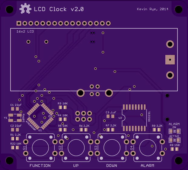
Now that I’ve spent some time working with SMD ATmegas, I decided to redo the PCB to make it all SMD. By moving the ATmega to the SMD version, I picked up some additional space on the PCB. That allowed me to add a 4th button to the PCB for the alarm function. In addition to the alarm button, there’s also a status LED for the alarm. The LED indicates that the alarm is set. I can even make it flash when the alarm is active. I could either use the Alarm button to enter the alarm menu to set the time, or add the alarm time to the main menu and use the alarm button as a snooze or a simple on/off toggle. Skies the limit!
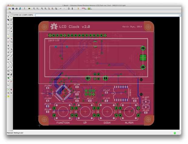
Since it's all SMD, I included an ICSP header for bootloading the ATmega, as well as an FTDI header for uploading sketches.
Another change that I made was to use a USB connector for power. I had a hard time finding a vertical power jack. All the vertical power jacks that I found were panel mount. I haven't seen one that can be soldered to a PCB vertically. Making a horizontal connection uses up a lot of space on the PCB and requires a huge cutout on the acrylic; as in version 1:
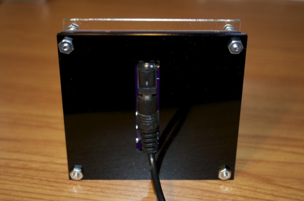
A USB connector is perfect. I can mount it vertically and use any old USB cable and 5V USB charger to power the clock.
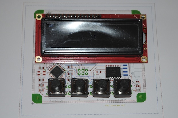
With the PCB finalized, I printed it out to make sure that all my spacing was OK.
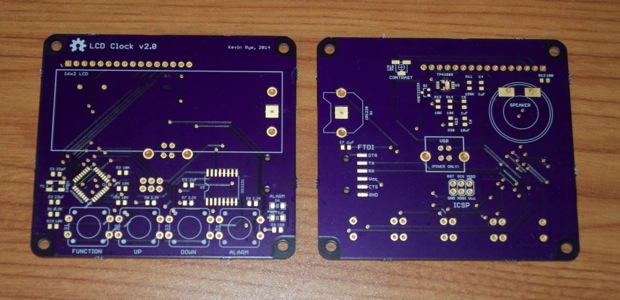
I then submitted my PCB to OSH Park to be made.
After a few weeks, my PCBs arrived.
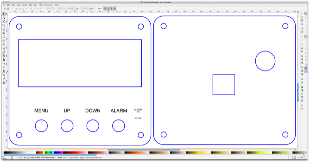
As far as an enclosure, I chalked up some acrylic panels in Inkscape and had them laser cut by Ponoko. I also had the names of the buttons etched into the acrylic.
It’ll probably take a week or two to arrive. So in the meantime, I can jump on the
7490 clock makeover.
See this project from start to finish: LCD Clock Version 2 - Design Decisions Mini Audio Amp, Take 1… and 2 Mini Audi Amp - Version 2 Build LCD Clock Version 2 - Part I
LCD Clock Version 2 - Part II
