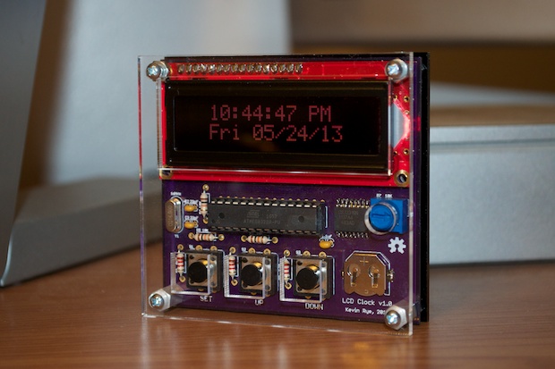
I was really pleased with the way that my
LCD clock turned out. Being my first Arduino project, I was a little nervous that it wouldn’t work, but I totally nailed it! There were a few trials and errors in making a stand for it before I figured out how to make a laser-cut enclosure for it. In the end, it turned out great and it works like a charm. I’m very proud of it. Seeing it come out as well as it did really encouraged me to push forward with more and more ATmega-based projects.
I’ve seen so many cool projects online that the makers have just screwed to a piece of wood or thrown in a crappy plastic box that’s way too big for it. That just looks horrible. How can you spend so much time and effort designing a PCB, getting it fabbed, assembling it, to in the end glue it into a cardboard box? Seems silly to me. I like all my project to have a well-finished look; complete with stand and/or enclosure. You’ve worked so hard on it, you should showcase it! I intent my finished projects to be around 30 years from now.
How long will your project last after you’ve enclosed it in cardboard and duct tape? (Yes, I’ve seen it done.)
Being my first Arduino project, I didn’t know it made better sense to design the enclosure in tandem with the PCB. I figured I’d just make a stand for it after it was assembled. I didn’t realize how hard it would be to design a case to fit it rather than designing the PCB to fit the enclosure. It’s so much easier to design a PCB to fit an enclosure than it is to design the enclosure to fit the PCB. (In my experience anyway.)
I decided to design “Version 2” from the start with the enclosure in mind. I was so pleased with the Version 1 of the clock, that it only made sense to take another look at it and find out how I could make it better. When I descried the first clock, I didn’t want to overcomplicate it or get in over my head, so I designed it to be the bare minimum. With Version 2, I’d like to include some of the features that I left out.
With that in mind, I made a list of things that I wanted to improve/add:
- Design PCB and enclosure in tandem
- Smaller DC input jack
- Mostly SMD components
- Include alarm feature (speaker / amplifier / alarm status LED)
- Include temperature sensing
As far as the alarm, I need to add an amplifier. I thought about just simply adding the
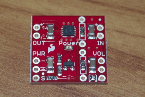
SparkFun Mono Amp Breakout Board as a daughter board similar to how I did it on the
SpeakJet board. But that seemed kind of lame. I didn’t want to “wimp out” by including it as a daughter board. I really thought that at this point, I should be able to incorporate the design into mine. Not to mention, there’s a few extras on the breakout board that I don’t need as well as hookups that I won’t use. As small as it is, for my purposes, it’s still bigger than it needs to be.
I made a list of the components that I need and priced them out. For a mere $1.36, I could buy the TPA2005D1 chip and all the 0805 caps and resistors. That’s a much better deal than spending another $7.95 on the breakout board. That of course all depends on whether or not I can actually solder the TPA2005D1 chip. It’s tiny! With 8 leads, it’s looks pretty challenging to do by hand. I’d hate to include it in the design and spend $40 getting the PCBs made to find out that it’s impossible to solder.
I decided to make my own breakout board to use as a test to see if I could solder it. I could have just made a tiny little PCB with a few 8-MSOP-sized pads for practice, but if it turns out I can actually pull it off, it would be nice to be able to actually use them. I slimmed the design down to the bare minimum of what I’d need: mono in, mono out, and eliminate the holes for the optional potentiometer. By doing so, I was able to make my breakout board a tad smaller than SparkFun’s. I subsequently ended up making it a little wider since I included a jumper to bypass the cap and resistor on the negative input so I can ground it if need be. In the end, it probably takes up the same area.
Mine vs theirs:
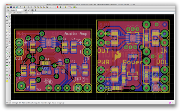
In any case, OSH Park gave me a price of only $3 for three boards. Even with all the parts I ordered from DigiKey, I can still assemble 3 breakouts for less than the price of one of SparkFun’s.
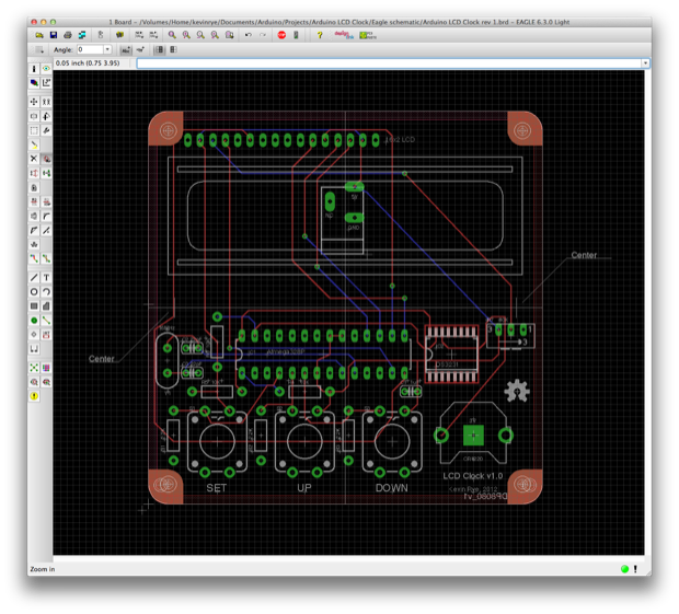
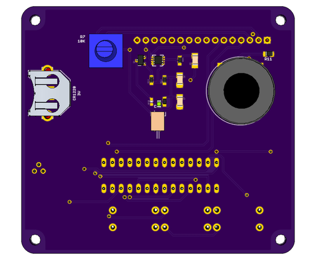
I got to work on the PCB for the clock. I started with my version 1 Eagle file, and went from there. First, I added the 80mm x 80mm
Sick of Beige template.
I added a speaker and all the components from the mono amp breakout. I added them to the back behind the LCD. I just hope that the speaker is loud enough to hear once it’s facing away. Maybe, like the SpeakJet, I’ll put a hole in the acrylic over the speaker. I don’t think it’ll be a problem. It’s not like I’ll be using it to wake me up. It’s just nice to know that it has the feature. If it’s not super-loud, maybe I can just use it as a reminder so when I’m sitting at my desk I don’t lose track of time; maybe even have it chime on the hour. Once I verify that I can solder the TPA2005D1 and that the design works, I’ll go ahead with it. If not, I’ll bite the bullet and just add the breakout board as a daughter board. So I have my fingers crossed that I’ll be able to pull it off.
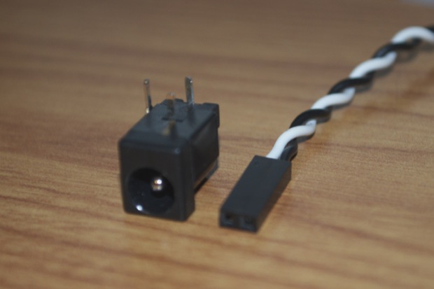
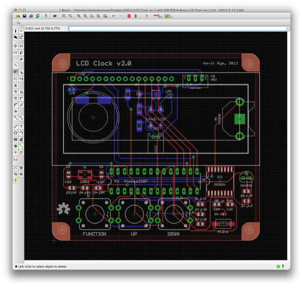
I changed all the resistors, capacitors, and the crystal to SMD parts. I ditched the huge 5mm DC input jack for a 2-pin JST connector. I might just use a 2-pin header and a Dupont connector. I’m still playing around with that. I thought about just clipping off the adapter’s connector and soldering the leads directly to the board, but I’d like to make it so that the adapter can easier be removed if need be. If I use a right-angle header, I should be able to connect power to the clock easily with a 2-pin female Dupont connector.
It’ll sit flush with the PCB and will make the clock that much thinner.
For version 1, I chose to use the DS3231 RTC over the more common DS1307 because of the DS3231s better accuracy. The better accuracy is due to the fact that the DS3231 does not use an external crystal like the DS1307. The DS1307 uses an external crystal of your choosing and will be effected by changes in temperature. Since the DS3231’s crystal is internal, it can compensate for the changes in temperature. It wasn’t until after I’d built the clock that I found out that you can actually poll the DS3231 for the temperature.
I thought it would be pretty cool to display the temperature on the LCD along with the time and date. Granted, it’s the temperature of the chip and not ambient air. I wondered if the chip temperature would be an accurate indication of the room temperature. Could I use it, or would I have to add an external temperature sensor?
The DS18B20 is supposed to be pretty accurate. (±0.5°C) At $4 bucks a pop, it better be! It uses the Wire library and only requires one digital pin from the ATmega. Each DS18B20 even has a unique ID, so you can have a bunch of them in your circuit all tied to the same digital pin and you’d be able to pick out a specific sensor and read the temperature.
Once I hit the prototype phase, I’ll compare the two temperatures and see if it’s worth it to keep the DS18B20 or if the DS3231 is good enough. I saved a bunch of space by changing the caps and resistors to SMDs, so I guess it wouldn’t hurt to include the DS18B20 in the design regardless. I even moved the DS3231 battery holder to the back to save even more space.
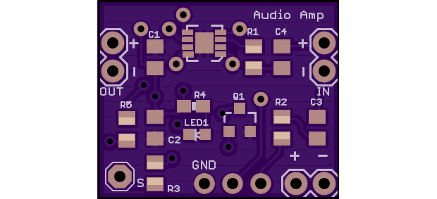
Here’s a 3D model that I made.
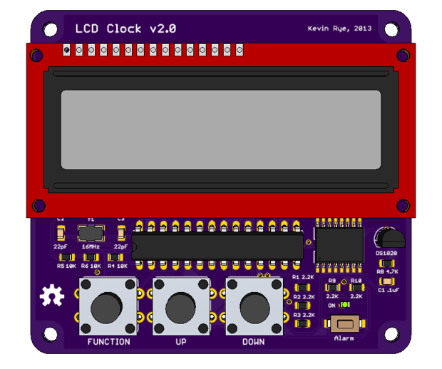
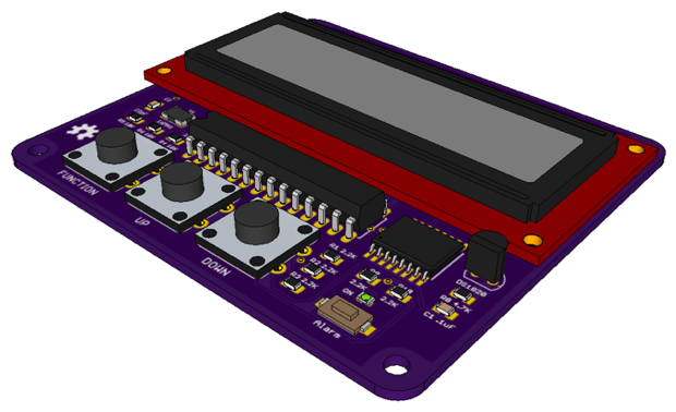
Finally, here’s what it’ll look like with the laser-cut acrylic front and back panels. It’s going to be sweet!

I had so much space left over after swapping the parts out for SMDs that I was able to trim the board to down to about 70mm x 80mm. So I’ll save a few bucks on the PCB too. I’ll then design an enclosure and have it laser cut by Pinoco. Once I receive the acrylic, I’ll make sure that the PCB and all the components fit before ordering the PCB. That way I can tweak it if something’s slightly out-of-place. Getting the acrylic cut seems to be the long-pole in the whole process, so it makes sense to get it done first. Like I said before, it’ll be that much easier to tweak the PCB to match the laser-cut acrylic than it’ll be to design the acrylic to fit the PCB.
See this project from start to finish: LCD Clock Version 2 - Design Decisions
Mini Audio Amp, Take 1… and 2 Mini Audi Amp - Version 2 Build LCD Clock Version 2 - Part I LCD Clock Version 2 - Part II
