I got my hands on a few really small 7-segment displays around 10 years ago. They are Ledtech LN2844R-15 orange displays. I pulled them off a defective motherboard for an old blood pressure monitor I found in the garbage. They measure 1.25" x .25". Tiny!
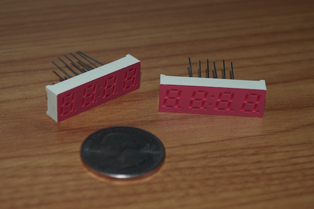
Back in the day, I didn't have the slightest clue as to how to multiplex them. Even if I could use a microcontroller, before the advent of the Arduino platform, the options were limited. I think PIC was around, but there was a steep learning curve, information was scarce, and the hardware (i.e., programmers) were expensive. Needless to say, they've been sitting in my parts cabinet since the day I sourced them.
I just put the wraps on
a new 7-segment clock to replace the innards of my old 7490 clock. Seeing how easy it was to multiplex those 7-segment displays, I thought I'd have a go at trying to make another
Mini 7-Segment Clock out of one of these teeny-tiny displays.
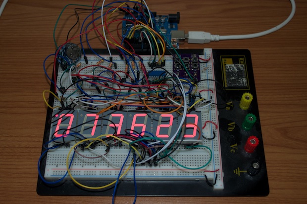
Most of the components that I used to prototype the new 7-segment clock were still sitting on my breadboard. I basically just had to drop the display in and figure the pins out.
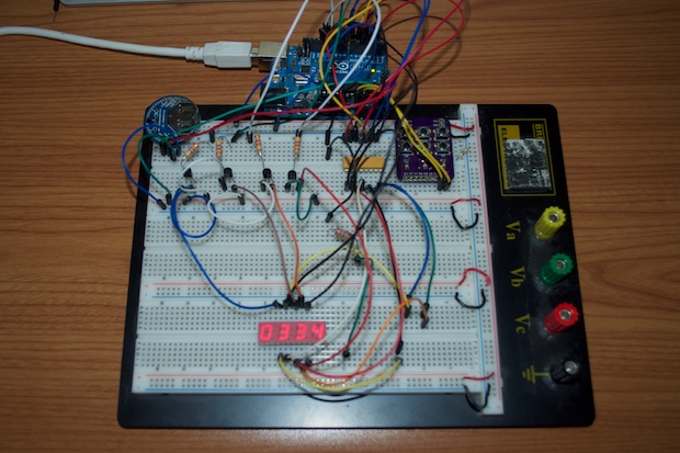
There was a catch. I searched online for a datasheet and concluded that the display is a common-anode display; unlike the common-cathode displays I've previously used. That meant that I had to swap out the NPN transistors for PNPs, and tie the emitters to Vcc instead of ground.
With the aid of the datasheet, I was able to determine what pin was what and connect everything to my Arduino. I modified my sketch and I was up and running in no time.
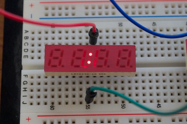
Something, however, wasn't right. As soon as I enabled pin 3 on the display, the colon and all the decimals would turn on. I couldn't seem to figure out how to shut the decimals off, and leave the colon on. It seemed to be all or nothing.
The datasheet said that pin 3 was for the decimal points as well as the colons. How can that be? How can they all share a common pin? The datasheet said the display was common-anode. How can these LEDs have a common anode and a common cathode?
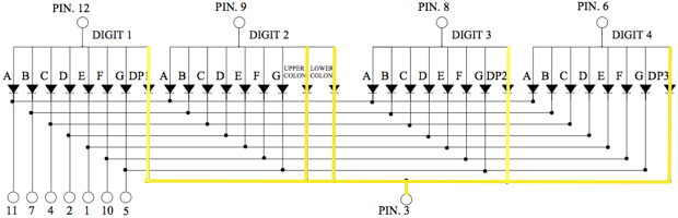
I searched online for a better datasheet and actually managed to find one despite the fact that it appears that this display is now very much obsolete. The datasheet actually had a schematic that showed how it's internally wired. Seeing how it was laid out, it made total sense.
If you look at the drawing below, you'll see the highlights I've made in yellow. The anode of each decimal point is tied to the anode of each associated digit. The anode for the colon is tied to digit 2. They all then share a common cathode at pin 3. Why they did it like that is a mystery. I think every other display I've used had the colon as a separate LED with its own pin.
To multiplex the display, I'm scrolling through digit 1, 2, 3, and 4 and illuminating all the segments for the number that's to be displayed. That means that as soon as I pull pin 3 low on the display, the decimal for that digit will always turn on. Since I'm scrolling through all 4 digits really fast, it appears as if all 3 decimals and the colon are on at the same time.
Since I want to use one of the decimals as a PM indicator, it appears that I'll have to treat the decimal and the colon as a separate digit and include them in the multiplexing routine.
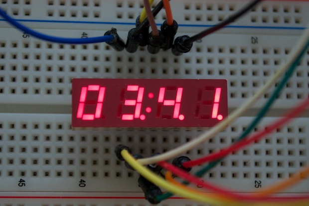
To test the theory, I shut all the segments off and sent digit 2 and the colon LOW. It worked. I just got a colon.
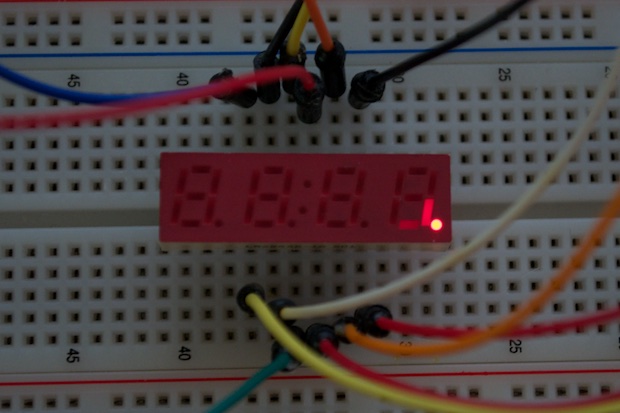
For the decimal, I shut all the segments off and sent digit 4 and the colon low. That gave me just a decimal.
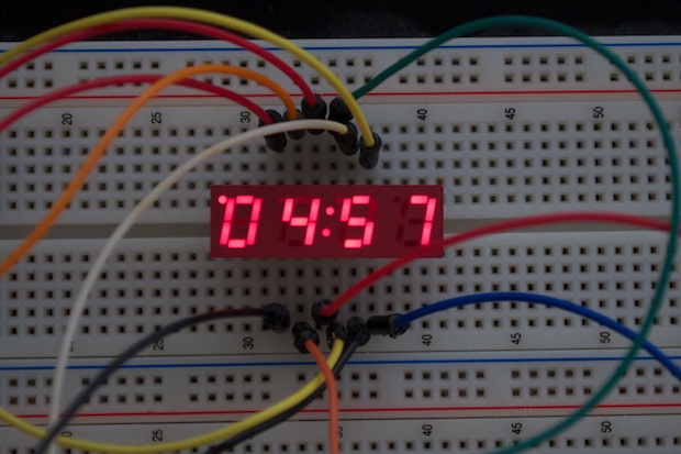
I was right. I have to multiplex the colon and the decimal. That means my multiplexing routine will have to scroll through: decimal, digit 1, digit 2, colon, digit 3, digit 4. I thought that I'd just be able to tie the LEDs to an output on the Arduino and send them high or low as appropriate. No such luck.
I also had to remap all the pins so that I could flip the display upside down. As you can tell by the time now displaying in the picture, it only took an hour and 16 minutes to figure the whole thing out and write the code. Not bad.
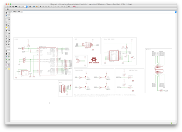
It was then time to create the schematic. I started off with my Mini 7-Segment Clock V2 schematic. The first thing I did was delete the display. I then worked in the transistors and made a new display. I was going to get fancy and actually make a new library for the part, but I decided to just drop in two 6-pin headers.
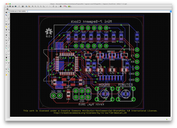
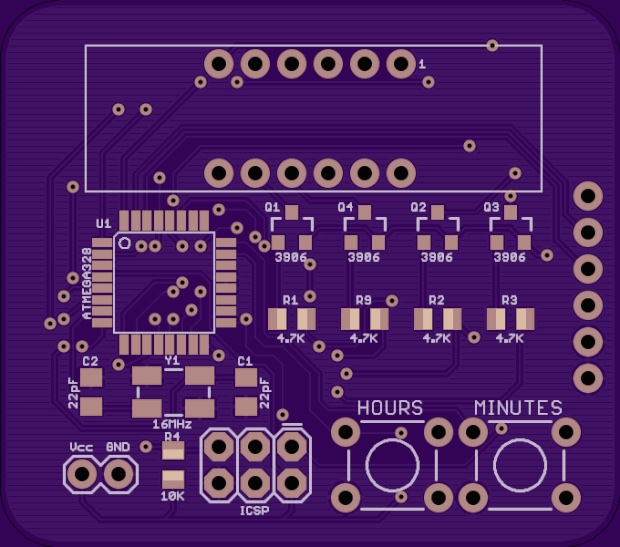
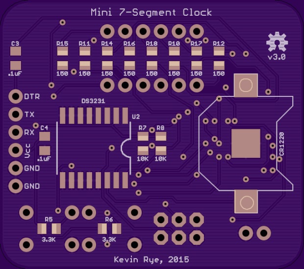
Even though the display is that much smaller than the one I used for the previous Mini Clock, I didn't seem to pick up that much space. I tried to shuffle things around as much as I could, but in the end it all came down to the mounting holes. They made the board way bigger than it needed to be. I decided to do away with them. I think I'll 3D-print some kind of case to put it in instead of the usual acrylic panels and board stands.
I suppose I could make it really, really tiny and delete the DS3231 and just count milliseconds, but I want it to be super-accurate. I'm also a big fan of a battery backup.
The PCB is so small, that it'll only cost $12.75 to have three made by OSH Park. Squeezing everything in and running all the traces was quite a challenge. I'll be pretty pleased with myself if this clock works.
 See this project from start to finish:
Mini 7-Segment Clock V3, Part I
Mini 7-Segment Clock V3, Part II
