I admit it: I'm a total geek. I love electronics, programming, 3D printing, 3D art, and vintage Apple hardware. I'm always juggling half a dozen projects. I also enjoy documenting it all: my successes, my failures, my experiences... and everything geeky along the way.
Mini 7-Segment Clock, Part I | Kevin Rye.net - Main
In order to try my hand at soldering some SMD components, I though a cool little 7-segment clock would be a cool (easy) starter project. I had all the intentions of starting it a month go. I hadn’t prototyped anything, but I did go as far as chalking up a board to see how small I could make one. I got distracted with the SpeakJet board and ended up using that as my SMD-starter project. SMD soldering can be a little tricky, so I figured the more I do, the better I’ll get. I decided to go ahead and push on with the mini SMD 7-segment clock. After a few little projects like this, I should be a master in no time!
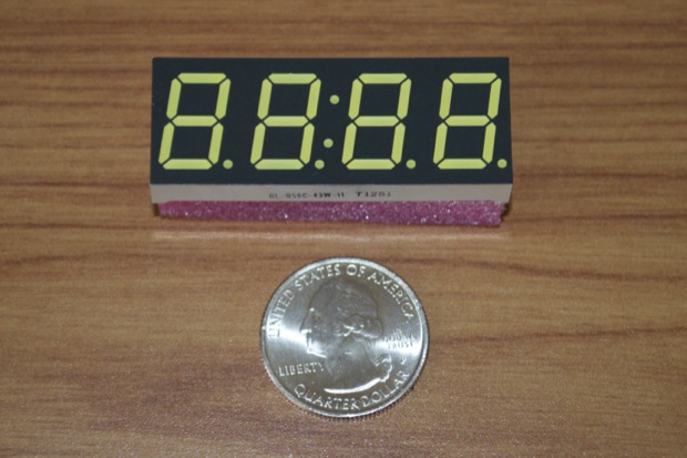
I had already picked up a common-cathode 7-segment display from Adafruit to start prototyping with. It’s pretty small. It measures .75” x 2” and was $6.95. It’s a pretty nice display.
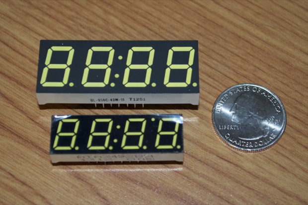
I was placing an order with SparkFun for the last-minute SpeakJet parts when I happened to notice that their common-anode 7-segment display was way smaller. (And way cheaper too!)
It measures .5” x 1.6” and was only $1.95. It should save me a little more space on the board.
Common-anode or common-cathode? The age-old question. I’ve seen a lot of people ask which is “better”. But it really has nothing to do with which is better.
Common-cathode means you ground the cathode and drive the segments HIGH. Common-anode means you apply positive voltage to the anode and drive the segments LOW. Choosing the right display depends on what driver IC you’re using. Depending on whether or not the output is active HIGH or LOW determines what kind of display you need to use. Since I’m driving my display directly with the ATmega328, it doesn’t matter what display I use. I just have to enable my pins to either HIGH or LOW as appropriate to the display I’m using.
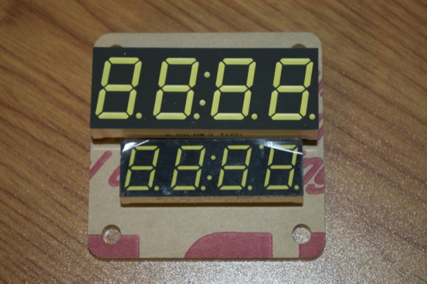
See? The Adafruit display doesn’t leave me much room for the ATmega and a few switches.
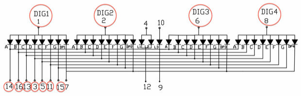
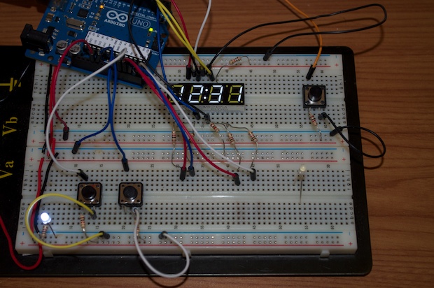
I got to work on the prototype. In order to multiplex the display, you need 11 pins on the Arduino. 1 for each of the 4 digits, and 1 for each of the 7 segments.
There are a few other LEDs left over. The decimals, the colon, and (specific to this display) an extra LED between the 3rd and 4th digits.
I found a sketch online that illustrated how to multiplex a display with the Arduino, without the use of any additional ICs. I wired up my display according to the data sheet and loaded the sketch.
It works.
Well that was fun, but I can do better! I don’t like the idea of just counting milliseconds when it comes to keeping accurate time. At least the sketch showed me the principles behind multiplexing. I wanted to rewrite the code to allow me to interface with a RTC, add an AM/PM indicator, and a better blinking colon. You can’t see it in the video, but the colon is really blinking. It’s just that the multiplexing is so fast that the colon ends up being barely visible.
But I knew the code would halt the loop for 500 milliseconds between each write. That’ll kill the multiplexing. I ran the code just to make sure. Sure enough: time displayed, no time, colon on, colon off, time displayed.
That’s not going to work. I could get fancy with the code, but I thought it would so much easier to just enable the 1Hz square wave on the RTC and hook the colon directly to it. I’ll also save an Arduino pin in the process.
To do that, I just added this to my setup function:
//set SQW to 1 hz for colon
Wire.beginTransmission(104);
Wire.write(0x07); // move pointer to SQW address
Wire.write(0x10); // send 0x10 (hex) 00010000 (binary) //1 Hz
Wire.endTransmission();
With that extra pin, I could use it to toggle the extra LED and use it as an AM/PM indicator.
For that, all I did was pass the hours from the RTC into a variable “hh”. I then did the math on “hh” to convert it to 12-hour format, and then toggled the LED as appropriate. I use “hours” later on in the setting function to set the RTC. The DS1307 can be set to run in 12-hour mode, but this is a simpler solution.
DateTime now = RTC.now();
  hours = now.hour(); //used to check AM/PM

  //pass RTC values into a variable
  hh = hours;

  //convert to 12 hr mode
  if (hours < 1) {
    hh = 12;
  }

  if ((hours > 12) && (hours < 24)) {
    hh = hours - 12;
  }

  //toggle AM/PM indicator
  if ((hours > 11) && (hours < 24)) {
    //PM
    digitalWrite(ampm, LOW); //LED on
  }
  else {
    //AM
    digitalWrite(ampm, HIGH); //LED off
  }
Sweet. We’re getting somewhere!
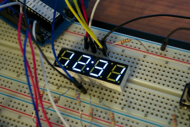
With multiplexing, all the segments are flashing on and off at an incredibly fast rate. With this sketch, the delay between writes is only 1 millisecond. Since they’re flickering on and off so fast, you get ghosting. If you look at the “1”, you’ll see how the rest of the LEDs are partially lit. In order to minimize the ghosting, I increased the delay between writes to 4 milliseconds. That way the LED is off just a little longer. Any more and a flicker is visible.
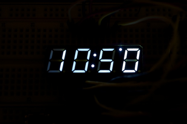
I also turned off the 1st digital when the hours are less than 10:00 o’clock. It seemed kind of silly displaying a “0’ otherwise. Turning off the 1st digital and changing the refresh rate really made a difference. There’s still the slightest hint of ghosting, but from a distance you can hardly tell.
Here’s a video showing the AM/PM indicator in action and well as the 1st digit dropping out when the time is less that 10:00. It’s hard to film the display with the refresh rate. It interferes with the camera. You can see the flicker as well as a halo, but that’s not there in “real life”.
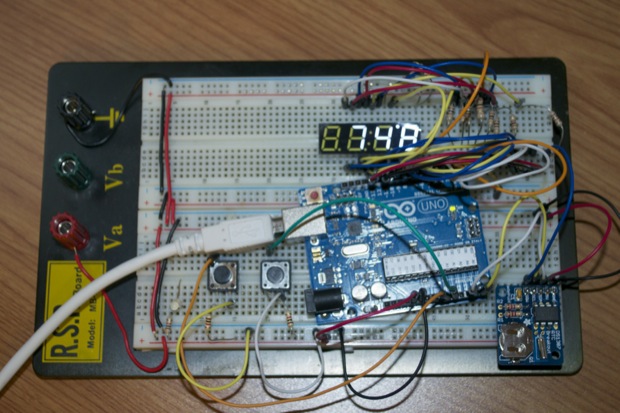
It would be nice to add an alarm. I’ll need a third button for that as a means of enabling/disabling the alarm.
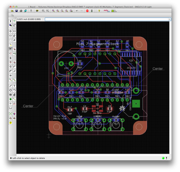
I got to work on a PCB to see how much real estate I have to work with. I want to make it the same 50mm x 50mm size that I made the SpeakJet board. It would be cool to make it really tiny and battery powered. Although, I don’t know how long a battery would last with all those LEDs running.
The DS1307 doesn’t support alarms, so I’ll have to switch over to the DS3231. Another problem is that the SQW/INT pin is either a square wave or an alarm interrupt, but not both. So if I use it for alarms, I’ll have to find another way to blink the colon. Unless, I stick with the DS1307 for the SQW and handle the alarms with code.
Decisions! Decisions!
In any case, it looks like there’s more than enough room to squeeze in the DS3231, a third push button, and a buzzer.