What a long two weeks it's been! I've been dying to get my hands on these boards!
They look awesome.
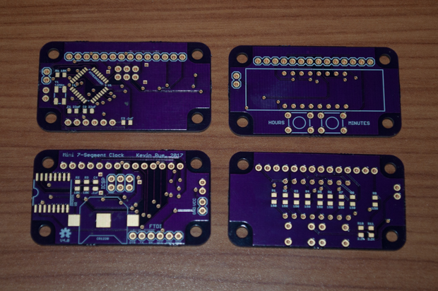
I'm really excited to put this one together. Not just because it's the 4th iteration of my Mini 7-Segment Clock, but because it's a totally new design concept. It's not just a smaller clock. This is the first mini clock where the display is actually mounted on its own PCB like a shield. So I'm really exited to see if I got it right.
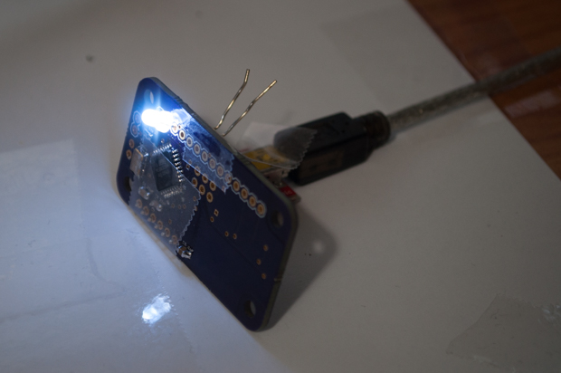
The first order of business was installing the ATmega stuff and bootloading the chip. I was able to successfully upload the blink sketch. I'm always so happy when that part of the assembly passes. If you can't bootload the chip, there's no point in continuing with the build. I always breathe a sigh of relief when I see that LED blink for the first time.
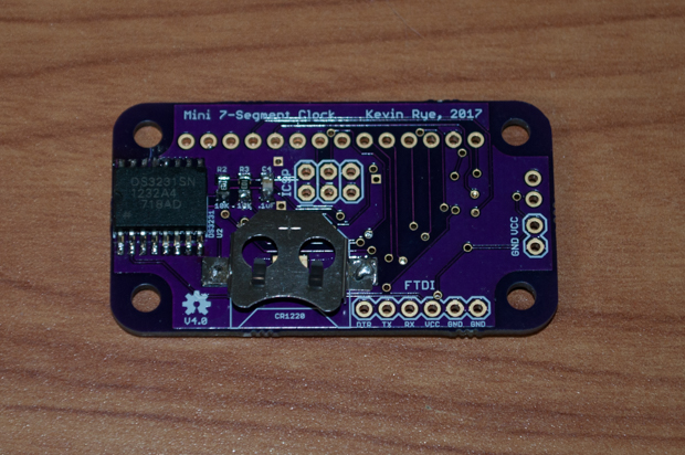
I then finished the main board by installing the DS3231 and the supporting components. I really wanted to put these boards in my reflow oven, but with parts on both sides, I figured I'd play it safe and solder it by hand.
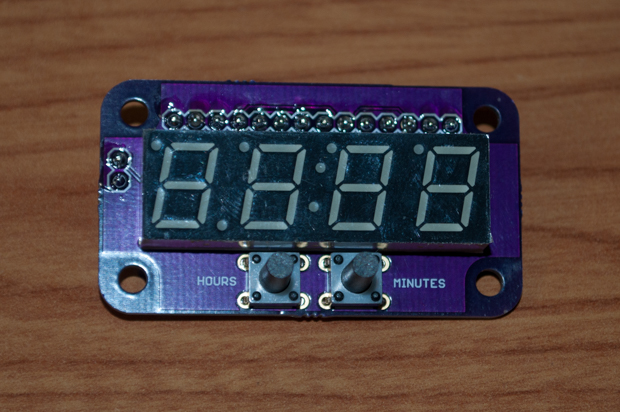
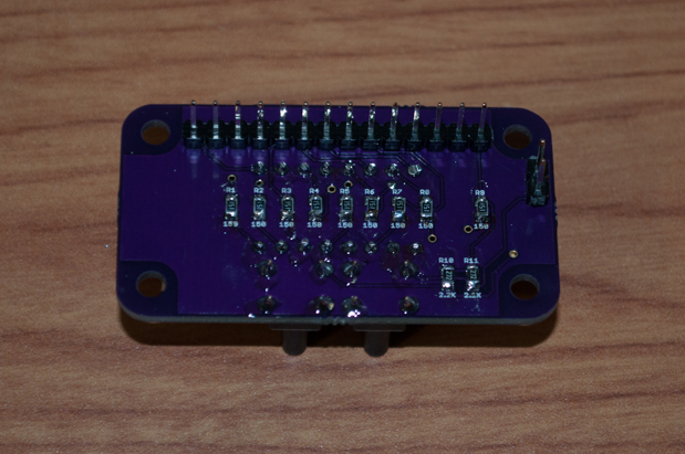
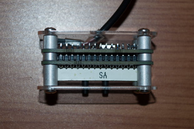
The display board was easy. It was just a display, 9 resistors, 2 switches, and some header pins.
The plan was to join the two boards together with a male and female header, but that would add a good 1/4" to the width of the clock. Despite using two PCBs, I still want this clock to be as small as it can possibly be. To that end, I decided to forgo the use of the stackable header, and just solder the two boards together with a single male pin header. This of course makes things permanent, as well as almost impossible to repair, but once the two boards go together, I really don't see a reason why I'd need such easy access to both sides of the boards. It's unlikely that it'll ever need to make a repair.
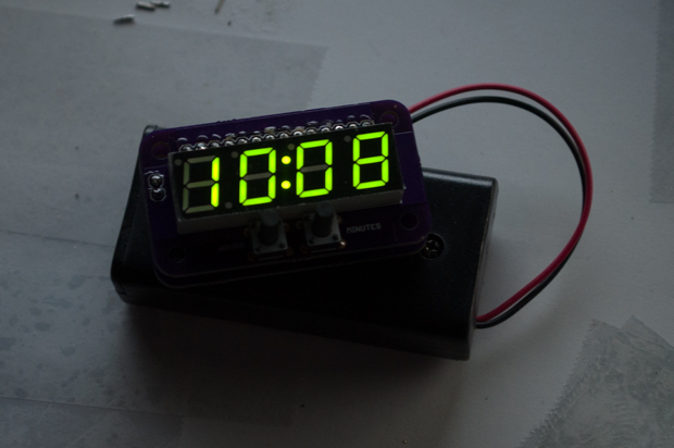
I soldered the two PCBs together, uploaded my sketch, and connected a 3V battery pack. It works! Awesome.
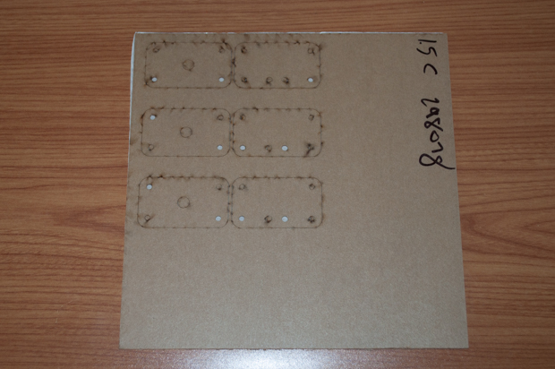
My laser cut acrylic arrived about a week before the PCBs did. What a tease.
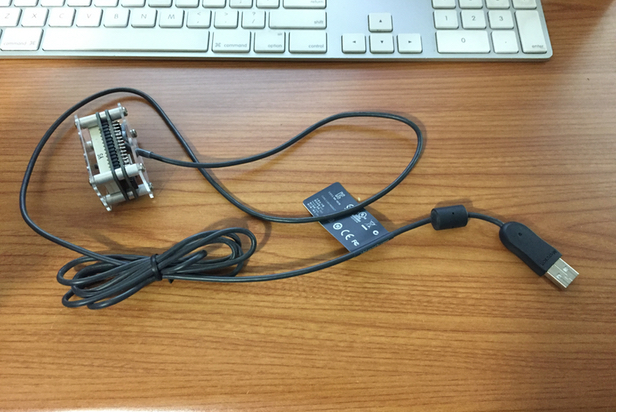
I gave it the longest USB cable I could find. I had an old mouse that was pretty grungy. Time to go.
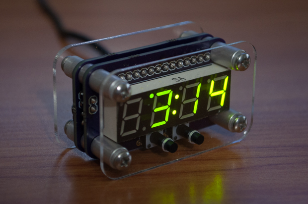
Everything went together perfectly with some 3/8", 1/8", and 1/4" threaded standoffs. I secured them together with 1/4" and 3/4" screws.
Wow, that looks really cool. I think it came out better than I had imagined.
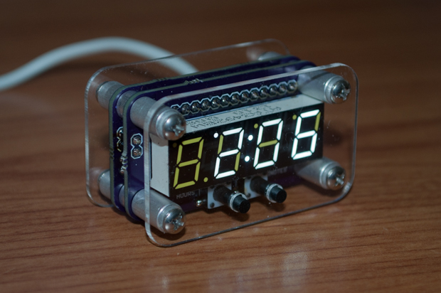
I even made a white one for myself since I had another display left over from the
Mini 7-Segment V1 clock.
I can't believe how fast I cranked this one out. It only took two blog posts to wrap it up!
See this project from start to finish:
Mini 7-Segment Clock V4 - Part I Mini 7-Segment Clock V4 - Part II

