I admit it: I'm a total geek. I love electronics, programming, 3D printing, 3D art, and vintage Apple hardware. I'm always juggling half a dozen projects. I also enjoy documenting it all: my successes, my failures, my experiences... and everything geeky along the way.
MEGA MINI Assembly, Part II | Kevin Rye.net - Main
If Google brought you here looking for the MegaMini by JK Devices, check here. If not, read on....
I left off with my MEGA MINI boards not working. I was banging my head against the wall trying to figure out what went wrong. I figured I’d shelf it for a week and look at it again another day with a clear head. I ended up getting busy with the Night Light 2.0 and the Bare Bones Arduino v3. Now that those are complete, it’s time to go back to the MEGA MINI and see what went wrong.
I posted my schematic on the Arduino forums and asked if someone could lend a second set of eyes and let me know if it made a stupid design error. It turned out I had .1uF caps on the crystal! Can you believe it? When I put all the caps into the schematic, I must have used the clone tool and forgot to relabel the ones for the crystal as 22pF. That mistakes carried all the way though to the PCB and I blindly soldered in .1uF caps without even questioning it. I should have noticed when I laid out all my parts that I didn’t have 22pF caps. I guess it was a “forrest for the trees” thing. It just goes to show that sometimes you just need a second set of eyes.
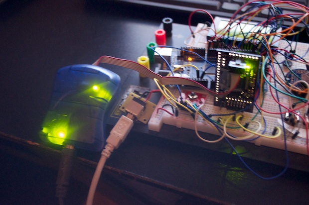
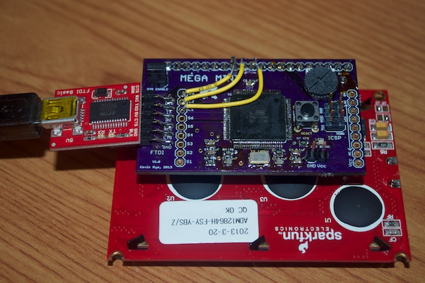
I removed the .1uF caps and replaced them with 22pF ones. I reconnected the PCB to Atmel Studio. I was so thrilled to see if pick it right up and write the bootloader without a problem. As a matter of fact, both boards worked great. I though maybe I had cooked the ATmega on the first PCB. Apparently, they are more robust than I had thought.
That’s awesome. That means I got all the ICP stuff on the PCB correct!
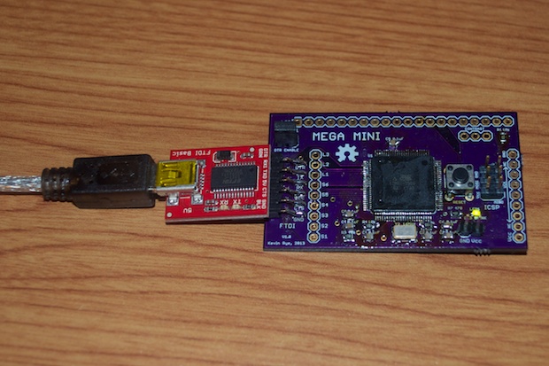
With the bootloader written, it was time to upload a test sketch. That will tell me if I got all the FTDI stuff on my PCB correct.
Blink, blink, blink! It works! I’m so thrilled that it works. I love not wasting $18 ATmegas!
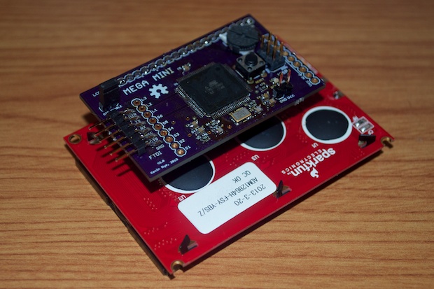
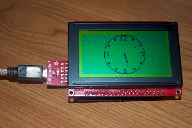
I have a header on the board for an LCD. Remember, this is supposed to be a stripped town version of the GPS clock that I’m working on. If I can get this right, then the final PCB for the GPS clock should be a snap.
Since this is just a prototype, I don’t want to permanently attach a $20 LCD to it, so I soldered in a female header.
Finally, I soldered in a 10K pot for the LCD. I was all set to try out some GLCD example sketches.
I uploaded a sketch, but sadly, nothing happened. I then rechecked my pinouts to the display and dang-it! I got them all wrong! I don’t know what I was on at the time, but I got all of them wrong. Maybe I looked at the wrong data sheet or something. Actually, I think what I did was confuse the fact that “physical pin X” isn’t the same as “digital pin X”. I think I just jumbled it all up.
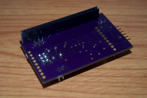
I though that it would be an easy fix and that I could just do it in code. I opened up the ks0108_Mega.h file in the GLCD library and remapped all the pinouts. I really goofed though and managed to use 3 pins that aren’t even outputs. To work around that, I just ran some jumper wires from the LCD header to the header for the Button Breakout Board and cut the traces on the PCB by the LCD header. I then remapped those 3 pins in the ks0108_Mega file. Problem solved.
Good thing this is just a prototype. Again, I’d rather make these kinds of silly mistakes on a $5 board than on a $50 one.
I recompiled and uploaded the sketch. Boom! It works. It really works!
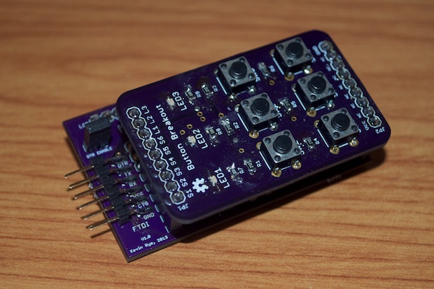
I then soldered in a few more headers for the Button Breakout Board and popped it in.
I then uploaded a new sketch that just sits there waiting for a button press. Once a button is pressed, it’s displayed onscreen. It’s just a simple test to make sure than I can interface with the ATmega2560 with the Button Breakout Board.
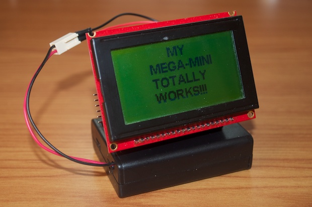
Here it is in action.
This was just supposed to be a proof of concept for the GPS clock; basically a trial run. However, it could very well be a finished project on its own. I could just put it in an enclosure and it would be good to go. With 256K of code space, I bet I could have it display a ton of cool stuff.
I’m one step closer to completing the GPS clock. I think it’s safe to go ahead and start working on the PCB and apply what I learned from the MEGA MINI.