Time for some PCBs!
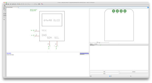
The first thing I needed to do was create an EAGLE Library for the generic 64x48 OLED display that I sourced from eBay.
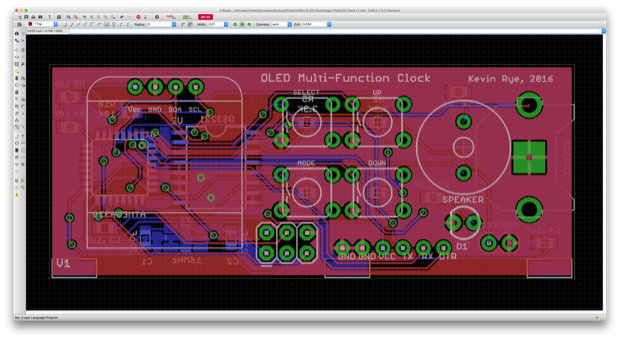
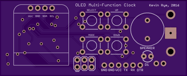
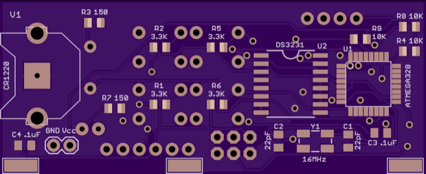
From there, I could then complete the PCB for the clock. Even though the board is tiny, it has the 4 buttons, the speaker, the DS3231 with battery backup, and some ICSP/FTDI headers. I also threw in an LED to serve as a low-battery indicator. The plan is to power the clock from a LiPo battery. With a timer and stopwatch function built in, it makes sense to make the clock portable.
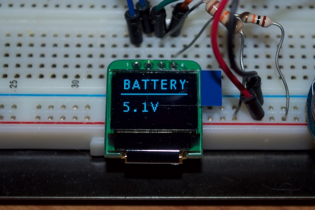
Just to make sure that the low-battery indicator was going to work, I went back to my sketch and added in another menu to show the battery level. Since my Arduino is plugged in via USB, it’s displaying 5.1 volts.
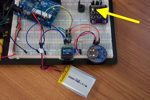
I then powered the Arduino off a dying LiPo battery. The display read 2.74V and the low battery indicator on my mini breadboard I/O board turned on. Looks like it works.
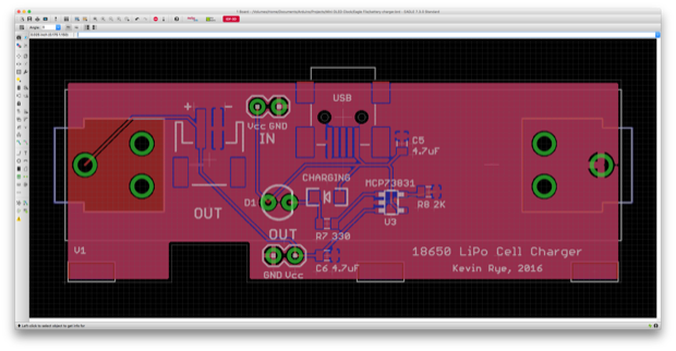
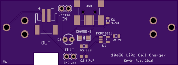
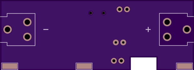
I killed my SparkFun LiPo battery charger a while back, so I have no way of testing if this is even going to work. I’m just going to cross my fingers that I can charge an 18650 battery with this circuit. I created a PCB to house the charging circuit and an 18650 cell. It has a few extra connectors on there in case I want to incorporate it into other projects down the line. With multiple connector options for power in and power out, it’ll be a little more versatile.
Both PCBs have some pads along the edges so that I can solder the boards together along the edges in an “L” configuration. I exported the boards from EAGLE to SketchUp and created a 3D model.
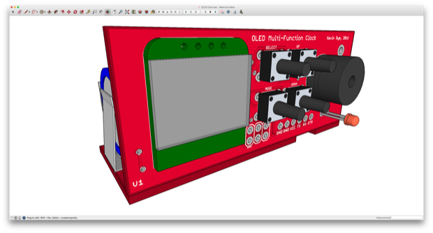
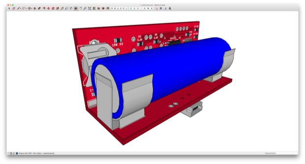
That’s going to look pretty cool. With a 3D model, I can get a better idea of what it’ll look like once it’s assembled. While the PCBs are being manufactured, I can get to work on coming up with some kind of 3D-printed enclosure.
It all looks good on-screen, so for a sanity check I exported the boards as .stl files and printed them out. Very crude, I know, but I just want to check the component clearance.
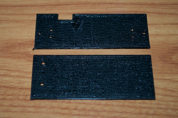
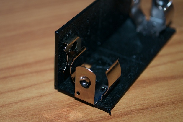
The boards will be soldered together at the edges, so I want to make sure that nothing comes in contact with the 18650’s battery clip. Since the coin cell holder is the tallest component on the back of the board, the rest should be fine.
With everything looking good, I placed the order for my boards.
Here are the OSH Park renders. Three boards only cost $3.80 after I applied a $10 coupon code that I had.
The battery chargers were $12.35 for three boards. Not bad.
I incorporated a cutout into the PCB so that when the boards are connected together, there’s a passthrough for the power cable, as well as a “charging” LED if I decide to make that visible on the enclosure somewhere.
 See this project from start to finish:
Mini OLED Clock - Part I Mini OLED Clock - Part II Mini OLED Clock - Part III
Mini OLED Clock - Part IV Mini OLED Clock - Part V Mini OLED Clock - Part VI
