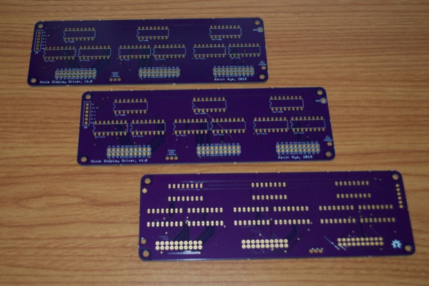
Since I ordered the
Nixie Clock Display and Driver PCBs back-to-back, I received them within a day of each other.
I waited until I had both boards before I started the assembly. I wanted to make sure that they both fit together nicely as I assembled them.
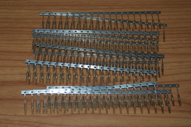
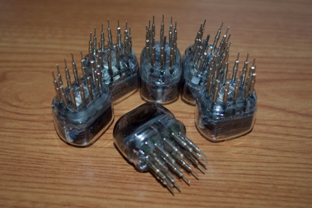
I didn't order enough nixie pins
last time to make two clocks, so I knew I'd need another 72 pins. I ordered them well in advance. It was a good thing too, because they came from overseas and it took a few weeks.
$7.69 for 250 nixie pins. Not bad; and it's enough to make 3 clocks.
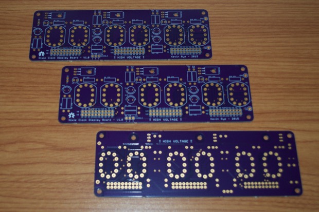
I first started with the driver board. It was an easy build, despite being 204 solder connections (not counting the 6-pin header). It's just 9 x 16-pin DIP sockets and 6 x 10-pin headers. It took all of 5 minutes to solder.
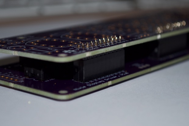
The best way to make sure that all the headers fit together and are nice and straight was to actually insert the pins of one board into the sockets of the other.
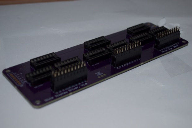
Nice and straight. There's nothing worse than soldering in a huge double-row header and then finding out that the mating header is off-kilter just enough to ruin your day.
Once they were all straight and flush, I soldered them in.
I then popped in my shift registers and my nixie drivers.
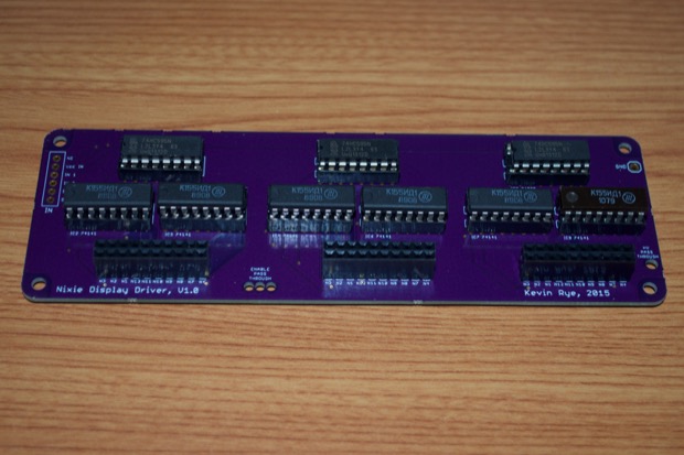
You'll have to excuse my ranting, but something that I found extremely annoying was that I ordered six nixie driver chips from one seller on eBay, and although all six chips are from the same manufacturer, the last chip on the right is of noticeable difference. A different production run? Different vintage? I hope whatever it is, there's no subtle differences between the chips to make a difference in the way the nixies are illuminated. I'll pretty pretty upset if I have one digit brighter/dimmer than the rest because the two chip types have a different current draw.
It just bothers me. If someone ordered six nixie driver chips, it's obvious that it's for a clock. Why would you not send six matching chips?
Anyway…
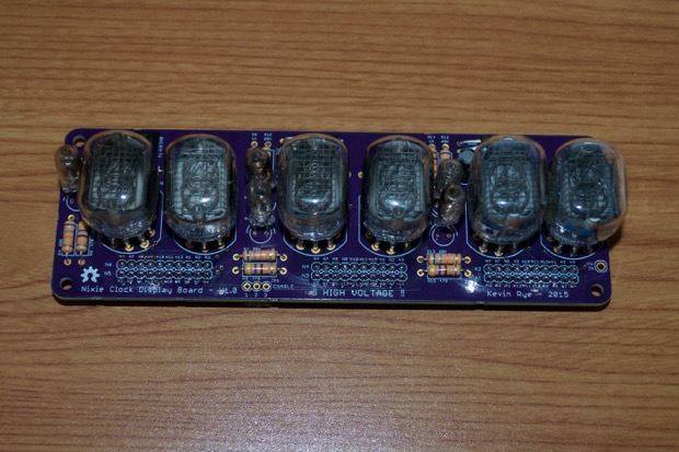
Once the driver board was compete, it was time to assemble the display board.
Is it just me, or does anyone else always make sure that all their resistors are facing the same way? I always make sure my tolerance band is to the right, or on the bottom
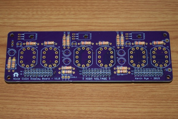
Don't think for a minute you're going to solder all those nixie pins in there and magically get the nixie tubes to just slide right in. There's just no way to keep all those pins straight and shimmy a nixie into them unless they're soldered in just right.
The best way to do it is to slide the pins right onto the legs, and then solder them in that way.
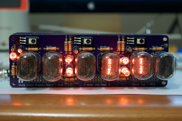
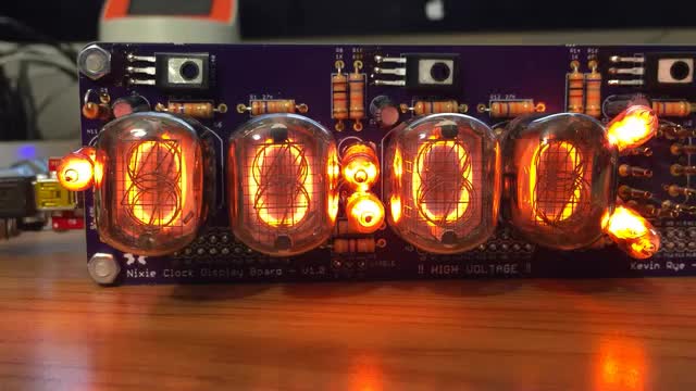
Very nice. All that was left was to solder in the decimal/colon nixies.
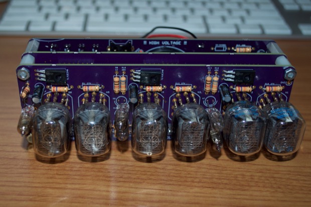
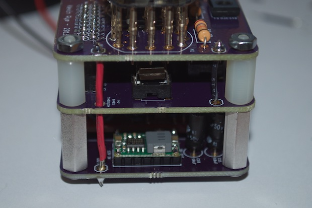
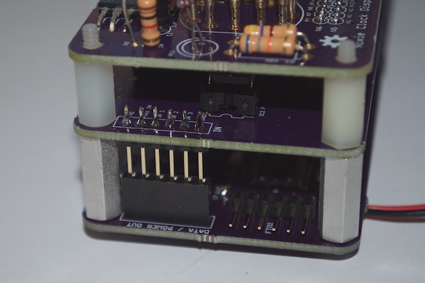
And there you have it, the three boards all soldered together and ready for the final assembly.
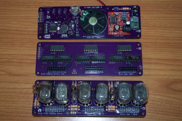
Please excuse the ugly mismatched standoffs. I didn't know what size I'd need in the end. Creating the 3D model in SketchUp gave me a pretty good idea, but I didn't want to spend the money on standoffs and shipping and end up with the wrong sizes. I figured for now I'd just use what I have and see if they fit. I might even end up just 3D-printing something.
That, and I'm still not entirely sure how I'm going to secure the assembly to the inside of the enclosure. I don't know yet if the front standoffs need to have a female or a male end. I'm thinking male, so they can screw into standoffs built into the enclosure.
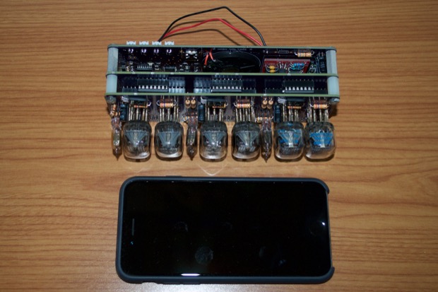
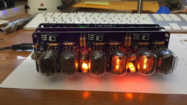
Up until now, it's been all 3D models and PCBs, and no real sense of scale. Now's the chance to see just how small this nixie clock is going to be. The footprint is just a little bigger than my iPhone. Not bad for my first nixie clock.
All that remained was the board-to-board connections. I tried to make it as easy to take apart as possible, in case future repairs are required, but some connections I'm going to have to just solder together.
I was going to just solder the enable-colon connections right to the board, but I figured I'd use a 3-pin connector at least at one end. It's a little bigger than I'd like it, but it's all I have on hand right now. Maybe in the future, I'll swap it out for a smaller Dupont connector.
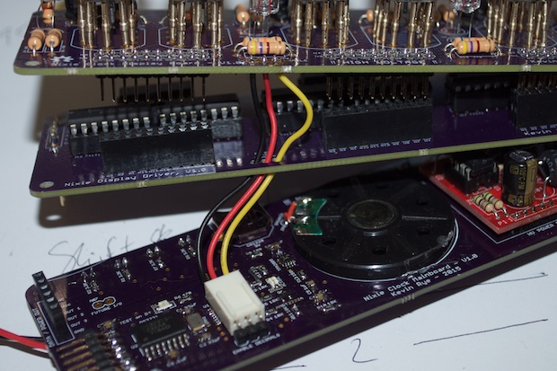
All the wires that go from board-to-board pass through holes in the middle PCB. This was because I didn't want any loose wires outside the area of the PCB. The thinking was that this would allow me to make the enclosure no more larger than the outline of the PCB. However, after seeing it built, I'm beginning to wonder if it was worth the effort.
The nixies aren't perfectly centered on the PCB, so if I want them to be centered on the front of the enclosure, I'm going to have to put in another 1/8 inch or so f dead space on the bottom of the enclosure. That in turn would give me plenty of room to run the required board-to-board wires. Oh well, I'll know for next time not to over engineer things.
For the data header, I went with a tall 6-pin female header for the main board. It's basically the same header you'd find on an Arduino. For the driver board, I went with extra long pins. It's just too bad that this is the tallest header I could find. I'm not a huge fan of the exposed pins, but it'll have to do.
Maybe I could just pull the pins out of another header and slide it on like a sleeve?
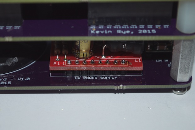
Lastly, I soldered the high voltage power supply onto the header.
I applied power and immediately noticed some issues.
My colon nixies weren't flashing. Actually, they wouldn't even turn on. I took some measurements and the voltage seemed to be fine. I found it strange that the 2 colon nixies that were hard-wired were on, and the three that ran through the transistors were not. It must be the transistors. What did I do wrong? That's one of the few things I actually prototyped! I ran a jumper from Vin to one of the nixies and it came on. It's the transistor. So what gives? I doubled checked the data sheet and wouldn't you know it, the EAGLE footprint I used had the pinouts totally backwards. I had to unsolder the three transistors, flip them, and solder them back in.
Success!
Here's a video of it in action. I'll be able to toggle the nixie on the far left as an AM/PM indicator, and the other two to display either a colon for the time, or a decimal for the date.
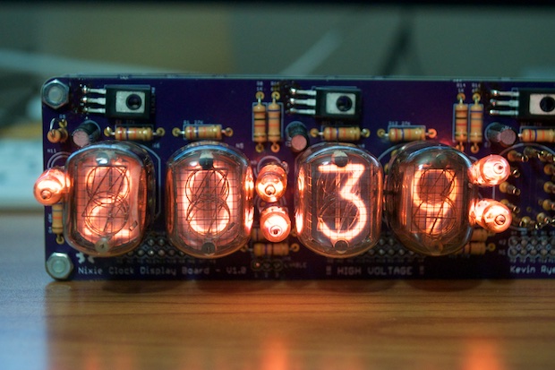
However, we still have a problem. Only two of my IN-12 nixies seem to work. Did I miss a connection? Bad solder joint? Did I totally screw up the design, the pinouts?
It was then that I seemed to recall that during
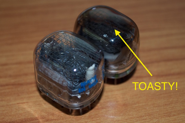
my previous experiments, I had issues getting some of these nixes to work. Since I was new to the world of nixies, I wasn't entirely convinced it wasn't my fault. As it turns out, 4 out of the 8 nixies that I purchased are dead.
I bought these nixies a good 10 years ago with the intent on making a nixie clock. I just never got around to it. Mostly due to the fact that I had no idea what I was doing. It wasn't until a few months ago that I dug these tubes out of my parts bin to discover that they are used. I thought these were "new old stock". I guess not. Maybe I was meant to replace them at some point and just forgot. Several of them are very dark and blackened; similar to when a regular light bulb blows.
In order to push along with development, I'm going to just use the 4 nixies that I found to still work, and populate the hours and minutes sections of the clock. The seconds will just have to wait until I can order a new set of nixies. I'm going to just order six new tubes and start fresh.
In any case, I figured out how to push some data through the shift registers and display numbers. I borrowed from an example I found online, but I heavily modified it for my clock. I was so relieved that it was just a matter of some dead nixies and not a screw-up in my design.
Here it is in action:
Once I figured out how to push numbers to the clock, it was jut a matter of feeding it the right numbers. Porting over all the miscellaneous clock code from one of my many other clocks was pretty much a cut-and-paste. It was a lot easier than I thought.
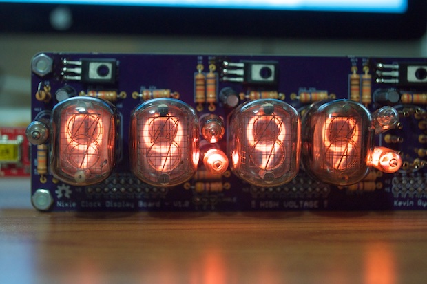
I went from counting from 0-9 to displaying the time in probably 20 minutes.
I know it's displaying military time, so a PM indicator is redundant, but I haven't put in the code to compensate for 12-hours yet. There is still much work to be done. I have to put in the code for the set buttons, the alarm, and the code to display the date when the Mode button is pressed. You know, the little things.
I also want to put in an animation or something that'll alleviate cathode-poisoning. Maybe I'll have something run at 2:00 in the morning for a few minutes when no one's around to see it. Something similar to the 0-9 counter.
See this project from start to finish: Nixies! Got My Nixies Powered! IN-12 Nixie Breakout Board, Part 1 Flashing a Nixie with an Arduino IN-12 Nixie Breakout Board, Part 2 Driving a Nixie with a 74141 BCD Decoder More Nixie Tube Experiments Nixie Clock 5V / 12V Power Supply Nixie Clock PCBs / EAGLE Upgrade Nixie Clock Main Board PCB Build Nixie Clock Final Build, Part I
Nixie Clock Final Build, Part II Nixie Clock Final Build, Part III Clock Button Panels
