Up until now, the nixie clock has been held together with a mish-mosh of assorted board stands that I've pulled from various hardware over the years.
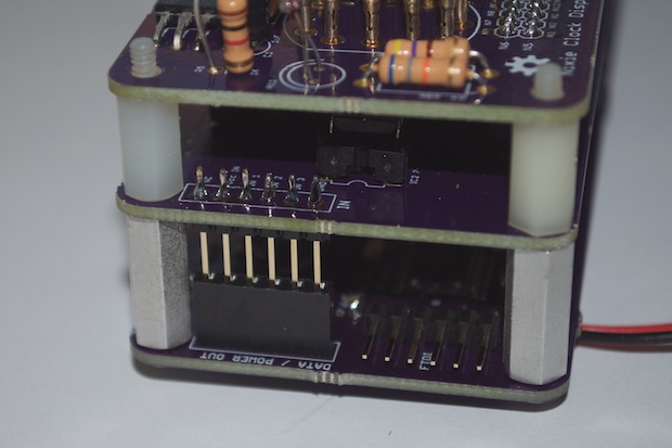
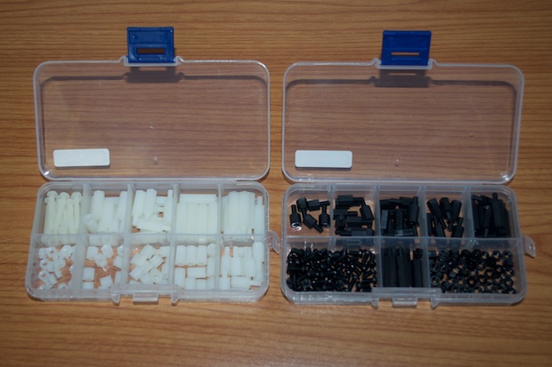
They served their purpose for the build-phase, but I'm not going to leave them in the final build. They're just too ugly. I also need some small 4 or 5 mm standoffs to mount the enclosure to the front of the PCB. If I'm ordering those, I might as well order a whole set. I jumped on eBay and found an assorted set of standoffs for just a few bucks. Metal would have been nice, but plastic will do. These are practically indestructible.
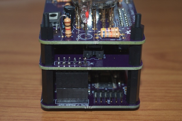
Nice. That looks much better. I also covered the exposed header pins on the data-out header with another female connector. I just pulled the pins out and slid it over the pins like a shroud.
As I mentioned previously, I purchased a lot of 8 nixies a decade ago on eBay. I didn't know that they were going to be a random assortment from different manufacturers. I certainly wasn't aware that they were used. It was so long ago that I don't know if I got ripped off, or if I was just an uninformed buyer at the time.
Out of the 8 nixies, only 4 worked. They're even of different brightnesses.
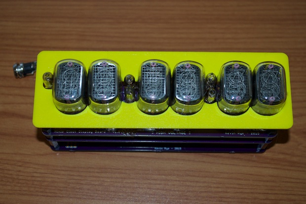
I immediately jumped on eBay and looked for some "new old stock". IN-12s are cheap. You can get them on eBay for $2. However, they come from overseas. Rather than save a buck and wait a few weeks for delivery, I opted to pay a little extra ($4 each) and purchase them from a seller in the USA. I had them in 3 days.
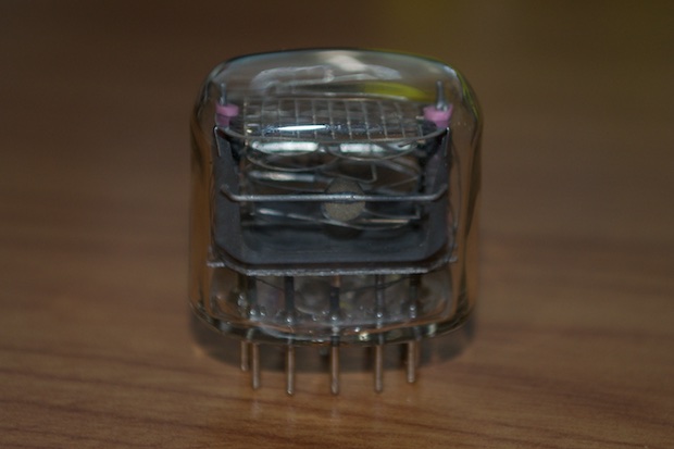
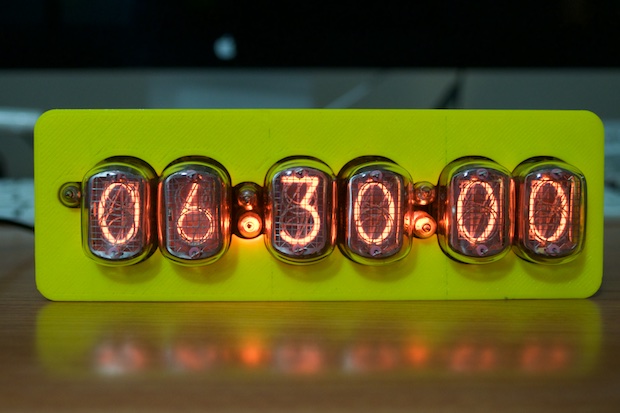
These guys are absolutely mint.
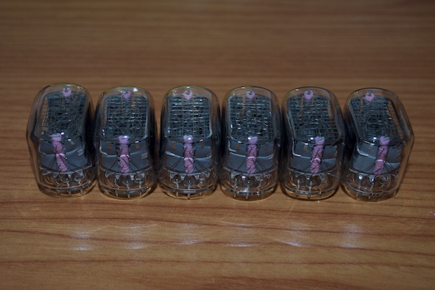
Compared to the blackened ones I was using before, these are crystal clear. They look awesome.
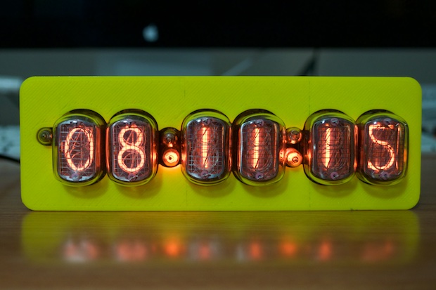
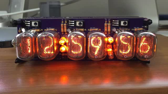
I've seen a few different font variations when it comes to IN-12s. I like the font on my "old nixies". In particular, the 5 looks like a 5. I've seen several images of nixie clocks online that use IN-12s that have a 5 that looks like an upside-down 2. This was probably done as a cost-saving measure. The same way that a 6 is an upside-down 9 (or vice-versa). That's one less filament you have to manufacture.
There's usually no way to know when you're buying nixies which one you're going to get. Unfortunately, I ended up with the 'upside down 2' type. I'm not sure how I feel about it. It does look kind of silly. Maybe it'll grow on me.
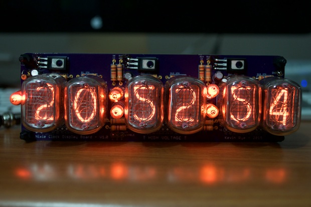
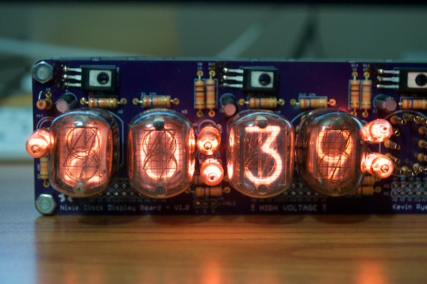
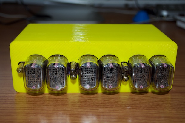
Despite that, they look amazing. There's no brightness variations like I had with the mixed bag of nixies I was using before. They all have the same beautiful orange glow.
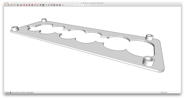
With the clock hardware complete, it was time to start working on the case. I took all the XY coordinates from the PCB and created a front panel in SketchUp. It's then that I noticed my spacing between nixes varied slightly here and there. I thought I double checked all that. I don't think anyone will notice that the seconds and the right colon are off by a millimeter.
I then printed the front as a test.
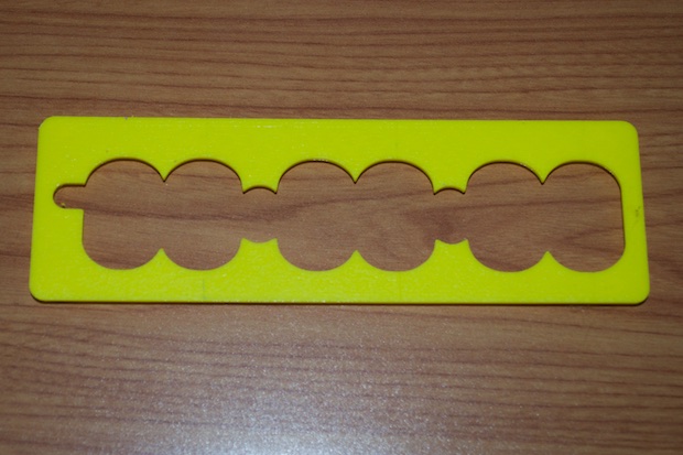
It looked pretty good, but there was only one way to find out.
Not bad at all. Another lesson-learned is that if you want each nixie to have its own cutout in the enclosure. You need to make sure that there's enough clearance on the PCB to allow it. The clearance that I left between nixies was too small to print.
I had to make one large opening for all the nixies. It doesn't look bad, but I would have preferred it if they each had their own cutout.
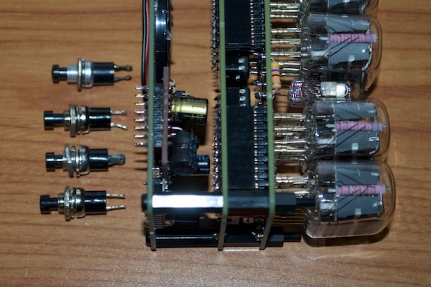
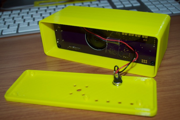
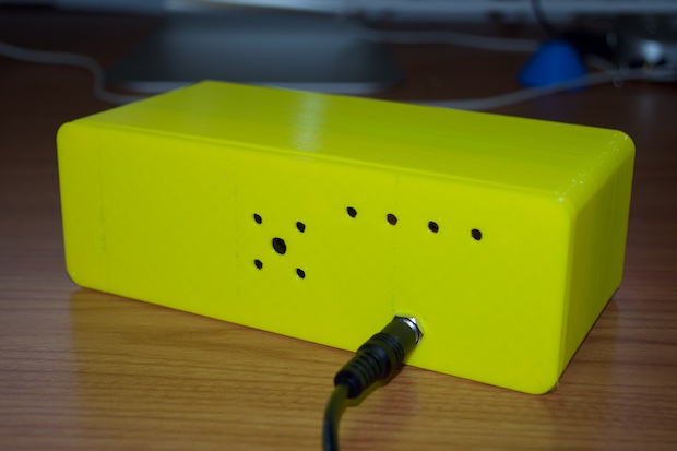
For the back, I need to make a hole for the four set buttons, power in, and the speaker. I was going to use these simple push button switches, but now I'm thinking they're kind of big. I don't want buttons on the top of the clock. I want to hide them on the back, so the buttons will have to be oriented horizontally. That'll add a good inch or so to the width of the clock. Then again, maybe I'm just being over-critical. The power jack is probably just as big. I just think these buttons look crappy. I could do better.
I thought about doing something similar to the button board that I hacked into my
GPS Clock.
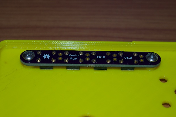
I could just solder 4 mini push-buttons onto a perfboard and hot glue it to the inside, but that's ghetto. I need a mini push-button breakout board!
I jumped into EAGLE and threw together a PCB. It's a tiny little thing, so it only cost $3.85 to have 3 boards made.
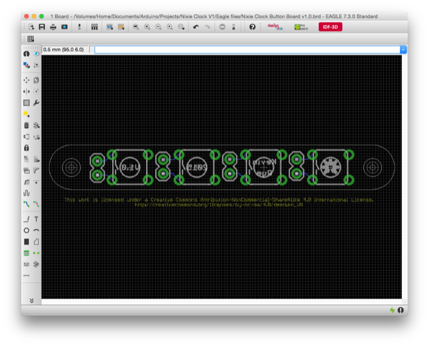
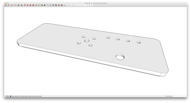
I then exported the PCB and took it into SketchUp so that I could match the holes up to the enclosure. I also put in a cutout for the speaker and the power input jack.
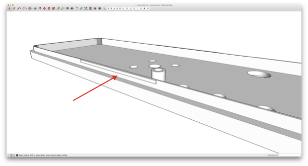
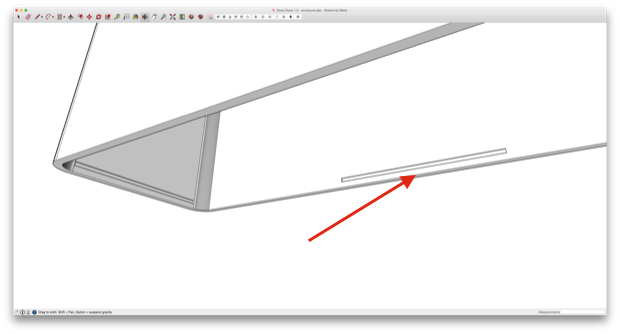
In order to attach the lid to the main housing, I opted to forego screws. I wanted to keep the enclosure neat and tidy and not have a lot of hardware showing. In order to clip the back panel on, I incorporated some little .5 millimeter tabs along the ends.
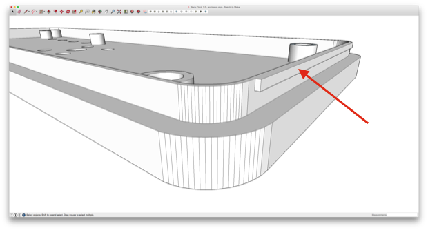
They'll clip into some notches incorporated into the main housing.
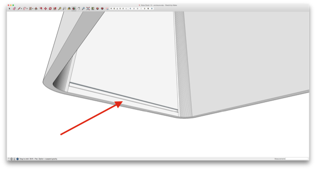
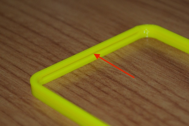
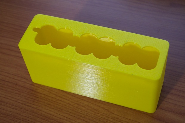
For a quick test, I printed out just enough of the main housing to see if the back panel clips on. Although it's a small .6mm cutout, you can definitely make it out as a feature.
I then printed out the back panel.
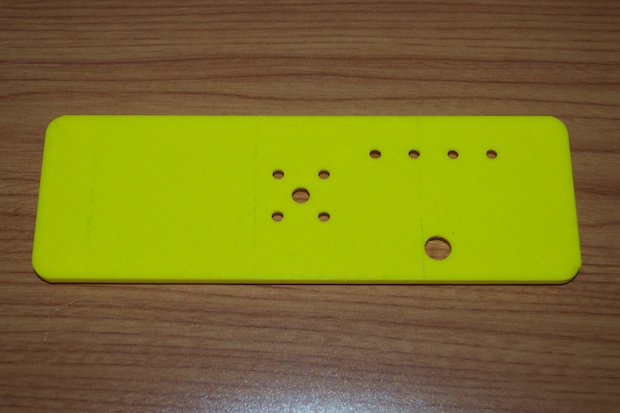
I nailed the holes.
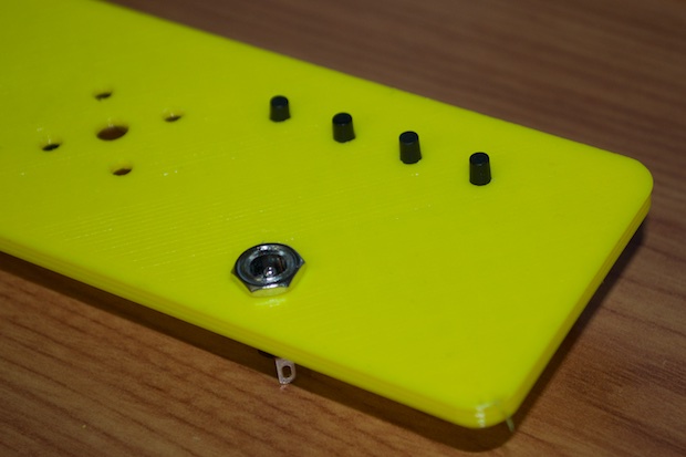
The notches came out pretty good too, but for the final print, I need to print them with supports. (Never mind the board stands, I didn't mean to leave those in the model.)
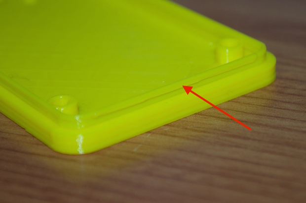
As far as the notches, they work really well. The two parts snap together pretty tightly. There's no way the back is coming off unless you really mean it to.
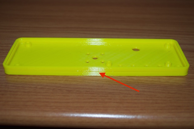
However, there is a little gap in the middle. I suspect this is because the mating part is only 2mm tall. There probably won't be that kind of warping when I print the entire case, but just to be safe, I went back to the model and incorporated another notch on the longer sides.
It was then time to print the full case and see if it all came together in the end.
There's just enough clearance in the back for the power jack. The button breakout (when it arrives) will screw into the board stands on the back of the enclosure.
Awesome. Now all I need to do is order a roll of wood-filled PLA and print it for real.
Almost 2 weeks later, my pushbutton PCBs arrived.
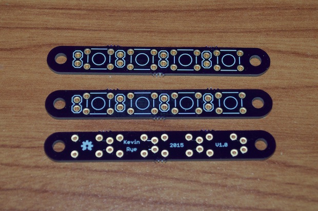
The PCB fits perfectly.
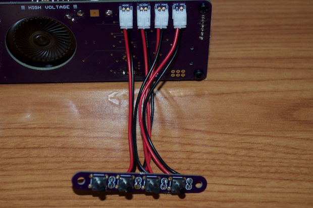
I soldered the JST cables to the switches and connected them to the clock.
Time for some code!
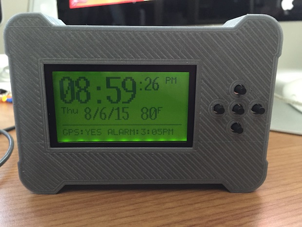
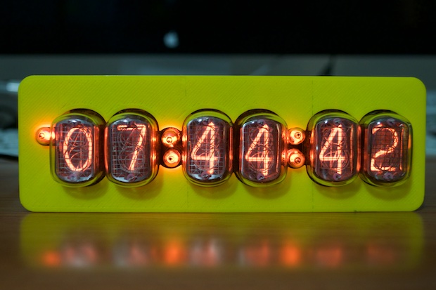
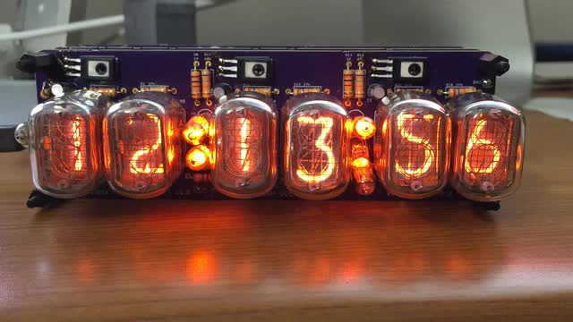
I've made some great progress. I have it displaying the time in 12-hour format. Pushing the HOURS and MINUTES buttons increments the hours and minutes. The seconds return to zero when the minutes are set.
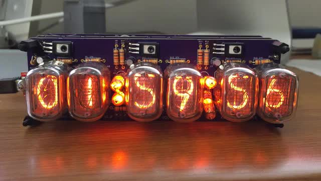
Pushing the MODE button on the back of the clock displays the date. In this mode, the HOURS, MINUTES, and ALARM buttons become the set month, set day, and set year buttons. Notice how the colons turn to decimals in date mode.
When in time mode, pressing the ALARM button displays the alarm time. The HOURS and MINUTES buttons set the alarm, selecting ALARM again toggles the alarm on and off, and pressing MODE returns you back to time mode. The colons are fully lit when the alarm is on, and display as decimals when the alarm is off. In addition, the alarm time is saved into EEPROM and read back in at power up.
Here's a sneak peek at some of the features. The audio stuff is a lot louder in person.
Chime on the hour:
Alarm tone:
Cathode Poisoning Animation. This actually runs at 2 in the morning for five minutes.
I'm finished with the code. I just have to print the case and wait for the button board PCB to arrive.
See this project from start to finish: Nixies! Got My Nixies Powered! IN-12 Nixie Breakout Board, Part 1 Flashing a Nixie with an Arduino IN-12 Nixie Breakout Board, Part 2 Driving a Nixie with a 74141 BCD Decoder More Nixie Tube Experiments Nixie Clock 5V / 12V Power Supply Nixie Clock PCBs / EAGLE Upgrade Nixie Clock Main Board PCB Build Nixie Clock Final Build, Part I Nixie Clock Final Build, Part II
Nixie Clock Final Build, Part III Clock Button Panels 
