I left off
last time with the notion that I'd be able to create a new IN-14-nixie clock based off the design that I used for my
IN-12 nixie clock. The plan was to use the main controller board as-is, and combine the driver and display boards. This proved to be more difficult than I had anticipated. The routing of the high voltage traces left much to be desired, simply due to the lack of real estate. I decided to not only use the original controller board, but the driver board too. After all, OSH Park gives you three boards for each order, so I have some left over from the last clock. I might as well use them up.
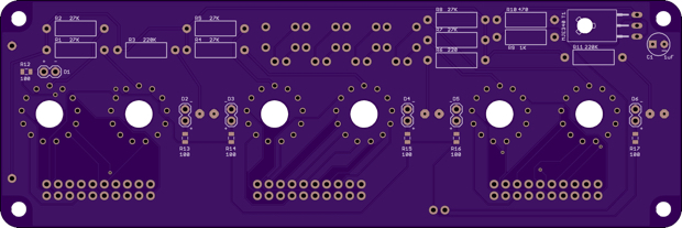
With that said, I set out to create a new display board. The image below shows the original boards from the IN-12 clock. The bottom two boards will remain as-is. All I'll have to do is redesign the top display board to accommodate IN-14s.
I started with the old schematic, swapped out the IN-12s with IN-14s, added some blue LEDs, and incorporated the four set buttons. The IN-12 clock had the set buttons on the back of the clock. I want to keep the case as small as possible, so I decided to mount the set buttons on the top behind the nixies.
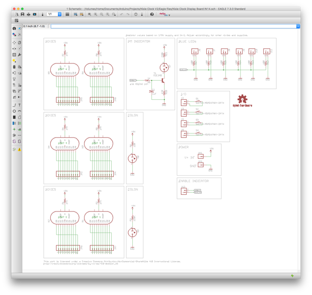
I then routed the PCB. There was plenty of space this time.
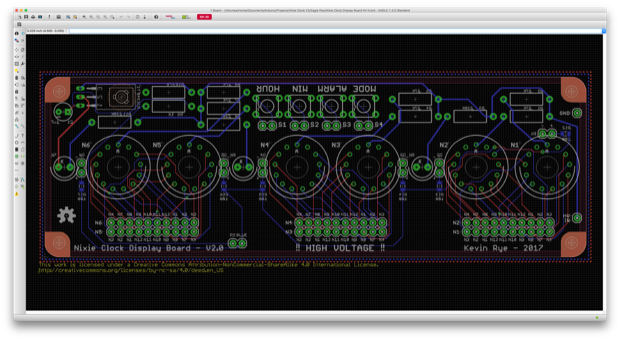
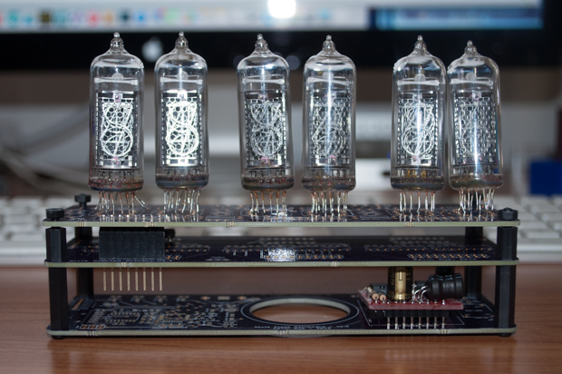
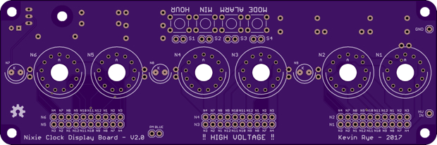
Here are the OSH Park renders. The plan is to mount blue LEDs under the nixies. I've seen a lot of nixie clocks with blue LEDs underneath the tubes and I've always liked the way that it looked. They'll be soldered in on the underside of the board and bent up into the holes underneath the nixies.
While I wait for my PCBs to arrive, I can assemble the main controller and drivers boards.
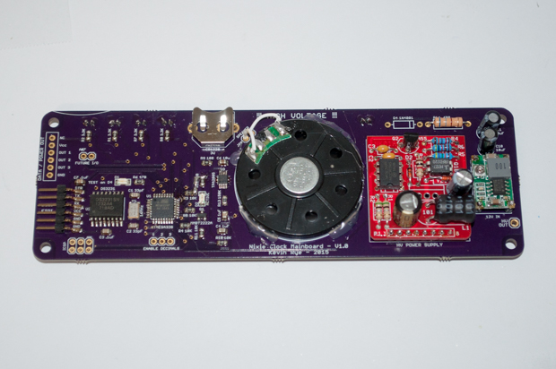
First up is the main controller board. I applied some solder paste and placed my parts.
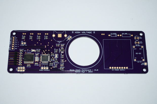
I then reflowed it in the oven.
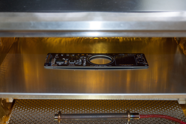
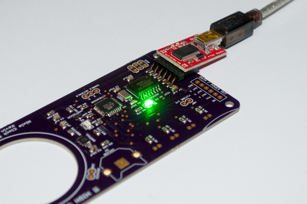
It came out awesome.
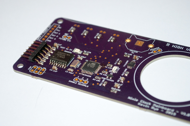
I then flashed the bootloader to make sure that it worked.
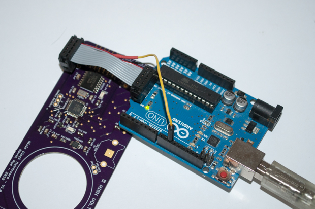
I then uploaded the Blink sketch! Success!
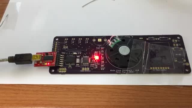
Next up was to make sure that the audio worked. There's no sense in soldering the power supply, the voltage regulator, and the other components if the audio doesn't work.
Nailed it!
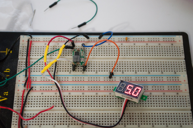
Before I could solder in the 5V regulator, I had to breadboard it and feed it 12V and trim the output down to 5V. If I did that in-circuit I might have run the risk of blasting the logic with 12 volts. If I had thought of it, I should have put a jumper on the PCB in line with the output so I could have cut off the regulator. That way I could have played with it in circuit. Maybe next time.
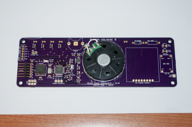
Knowing that all the logic worked, it was time to hot glue the speaker into place and solder in the rest of the components.
It was then time to assemble the display driver board. This was easy. It's all through-hole.
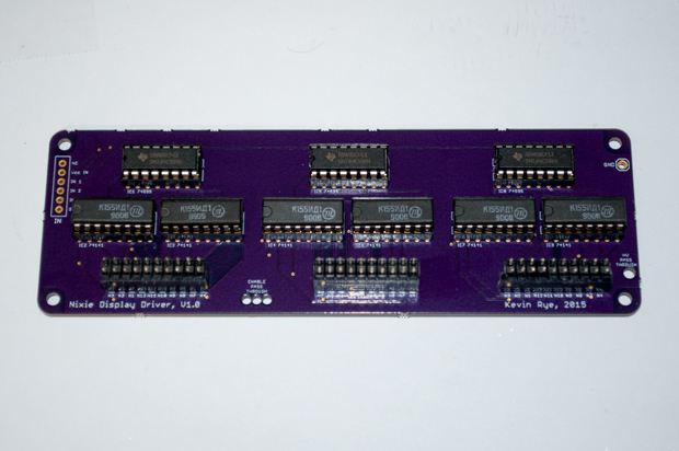
All done. For now.
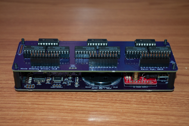
That's as far as I can go without the display board. The display board should be here in 2 days. I can't wait!
See this project from start to finish:
IN-14 Nixie Tubes Nixie Clock V2 - Part I
Nixie Clock V2 - Part II Nixie Clock V2 - Part III Clock Button Panels
