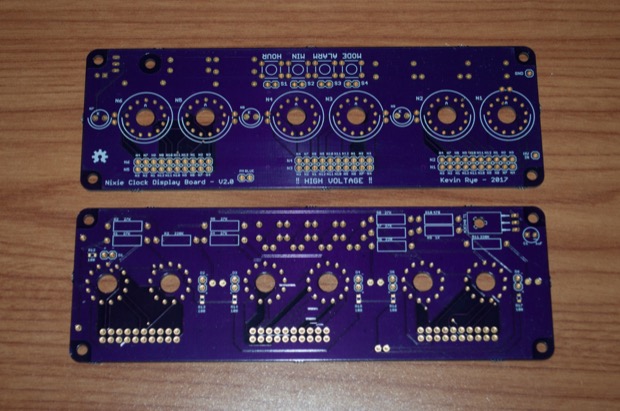
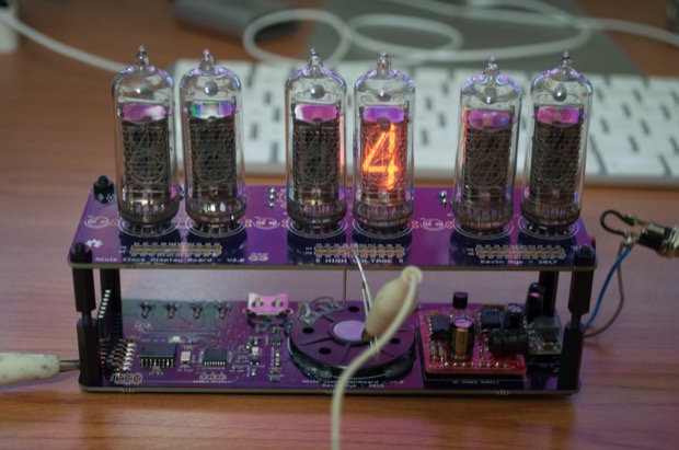
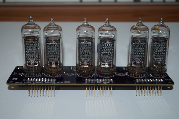
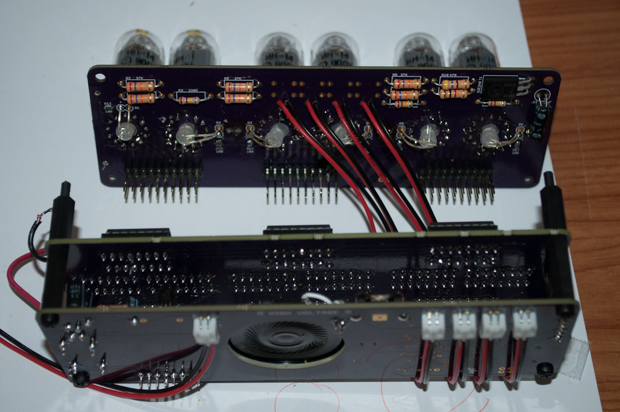
My IN-14 display board arrived quicker than I expected. It was only 9 days. It came out awesome.
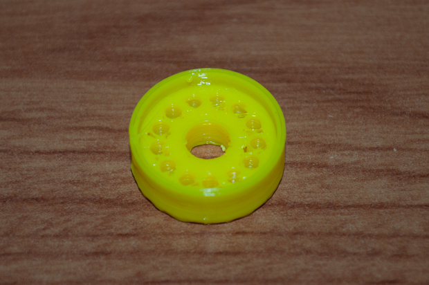
I like to socket my tubes in case I ever have to replace one in the future. Finding sockets on eBay is difficult, and expensive. I decided to try my hand at 3D printing my own. Easier said than done.
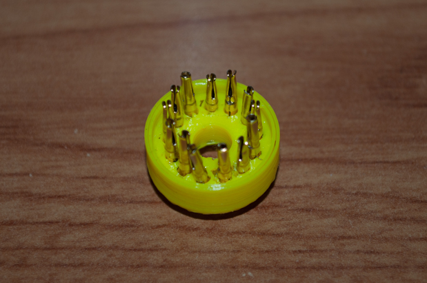
It was easy enough getting the pins in the holes, but trying to get the tubes in the pins was very difficult, and in the end proved to be an exercise in futility. The leads on IN-14s are usually rather long. These tubes are obviously used since the leads have been cut way down. Not to mention, there's solder on them. The leads are just a bit too short for the pins to properly grab them.
In the end, I just decided to solder the tubes directly to the board. The eBay seller stated that the tubes were new and tested, but seeing the state of the leads, I wasn't 100% convinced. Rather than solder all the leads, I decided to just solder the anodes so that I could test them out first.
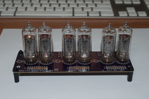
I then connected the main board and applied power. I then grounded each of the pins to make sure that all the digits worked. As luck would have it, all the tubes work.
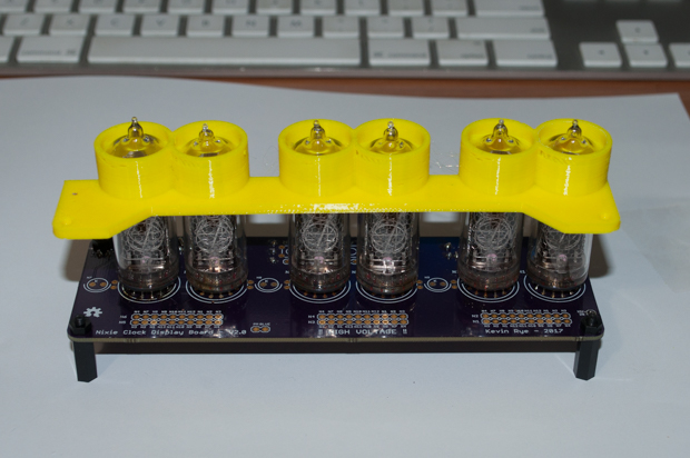
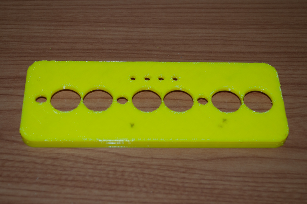
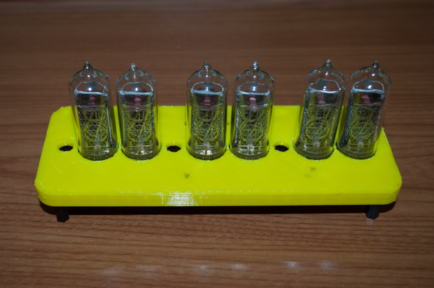
In order to keep all the tubes nice and straight, I devised a jig that I could slip over the tubes in order to keep them straight. I don't want my tubes looking like tombstones after an earthquake.
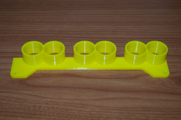
I made the holes just a tad too small. Needless to say, they don't slide all the way down. If I push down on the jig any harder, I feel I may shatter one of the tubes. That, and I'm sure it'll be impossible to pull it off afterwards.
It's good enough. All the tubes are nice and straight, and well aligned with each other.
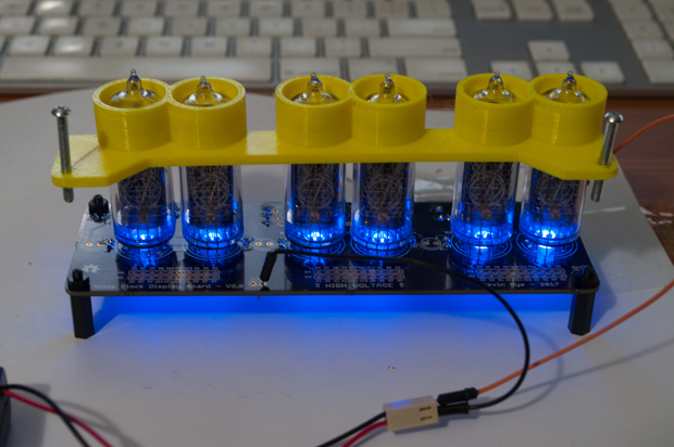
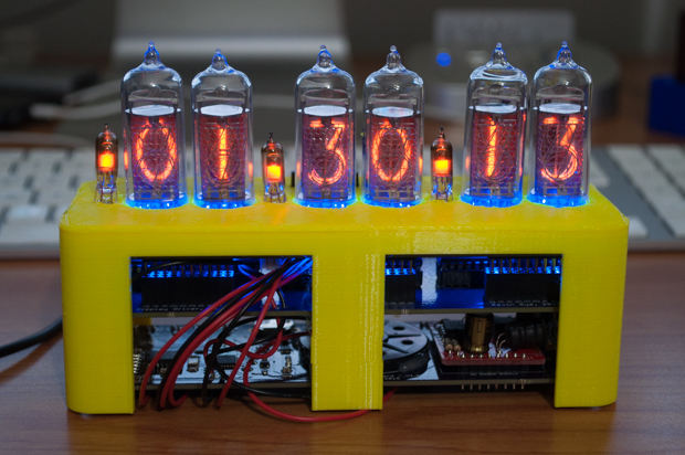
I then soldered the rest of the nixie leads and added the blue LEDs. Some of the LEDs are not as straight as they should be, but I'm sure it's fine.
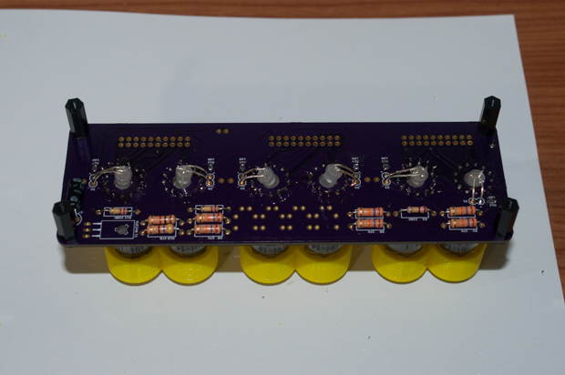
Using a battery pack, I applied power to the LEDs just to check them out. That looks awesome.
I can't solder in the IN-3 separator nixies until I make the case for it. I won't know how high they have to stand until the case is on. I got to work on prototyping the top first so I could nail down the hole placement.
Nailed it.
In my first nixie clock, the display board was connected to the driver board using standard-length double row headers. Unfortunately, adding the blue LEDs to the underside of the board makes it impossible for me to use these headers. They are no longer long enough.
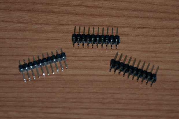
I had to order some longer headers.

These were actually too long. I cut them down about 3mm and soldered them in.
A perfect fit, and there's enough clearance between the chips on the driver board and the LEDs on the underside of the display board.
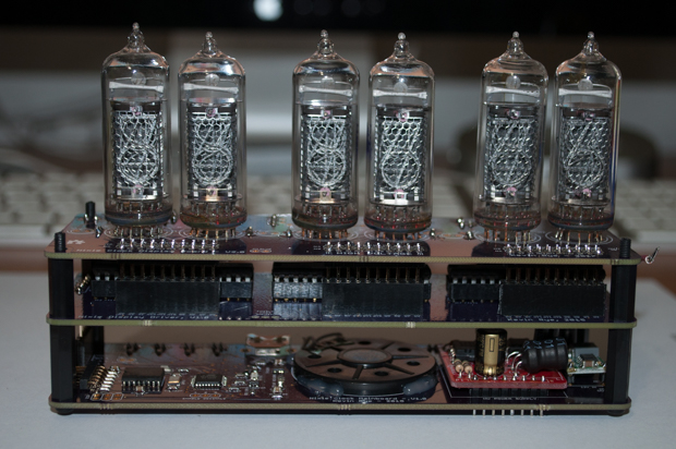
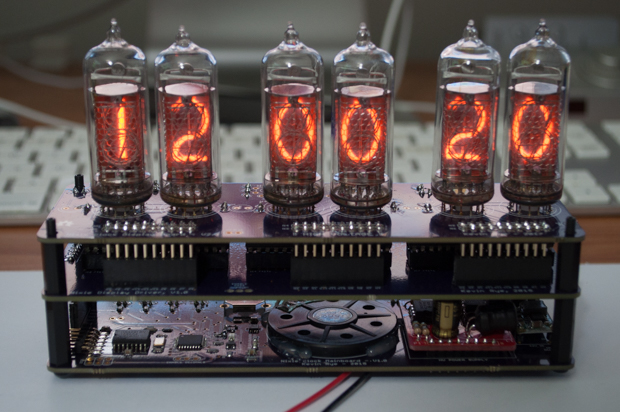
The moment of truth. I uploaded my sketch and verified that everything worked. So far, so good.
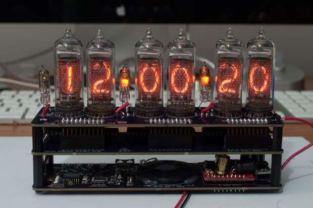
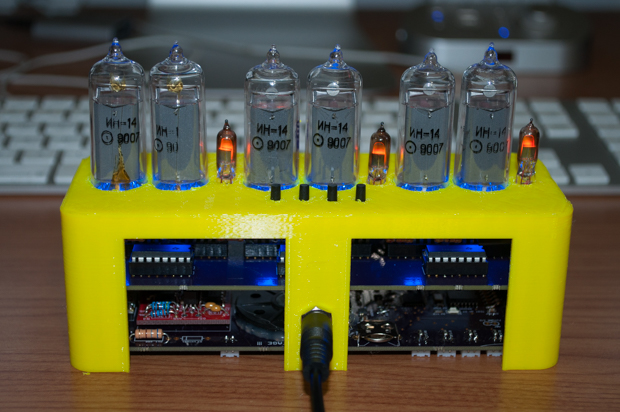
It was then time to solder in the IN-3s. Unfortunately, they are on the board backwards. Well, the footprint is facing the right way, but I think I mixed up which is the anode and which is the cathode when I connected them up in the schematic. I had to solder them in backwards and place some stripped wire insulation over one of the legs, and then twist them around so they are facing the right way. The insulation stops the leads from touching each other and shorting things out.
I then soldered in the button wires...
… and soldered in the buttons.
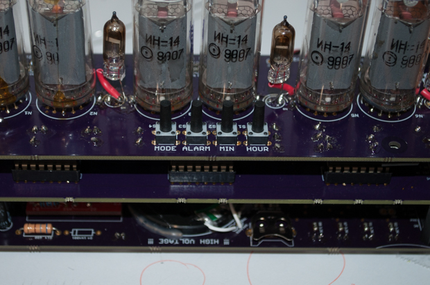
Looking good. Everything fits nicely.
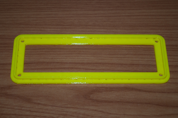
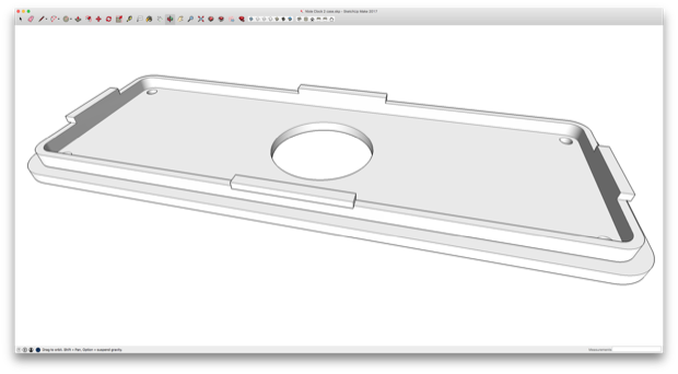
With all the electronics complete, it was time to finalize the case. I jumped back into SketchUp and got to work on the case.
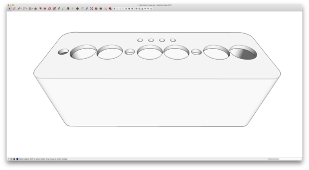
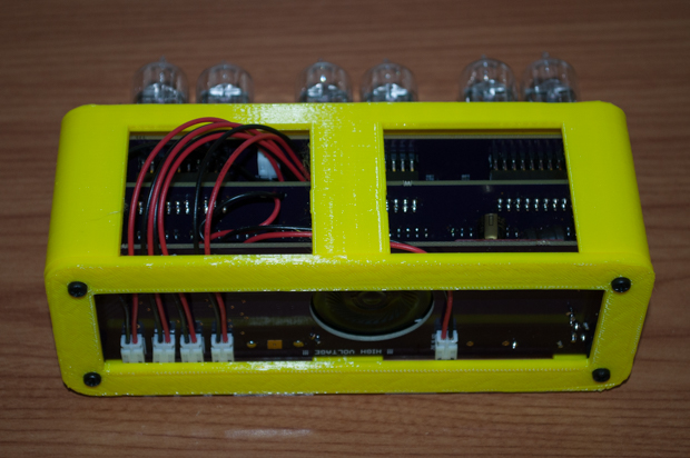
In order to save some time and PLA, I removed some sections of the walls. This will also help me see inside and gage how much clearance I have on the inside for squeezing in the wires and the power connector.
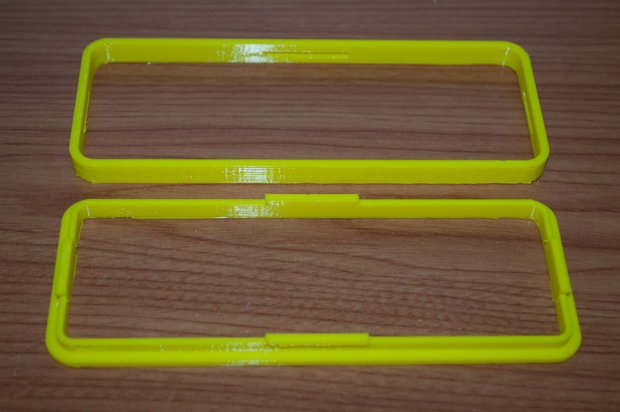
I then prototyped a bottom for it. Again, to save on time and material, I hollowed out the center.
It fits really well, but I think I might incorporate some notches on the inside so that the bottom sort of clicks into place.
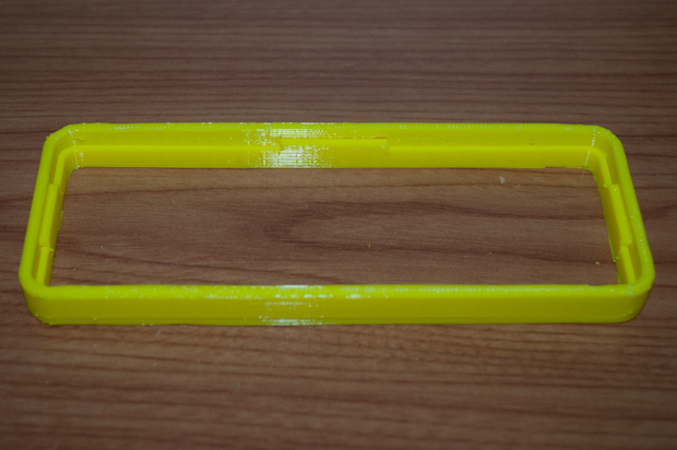
Something like this….
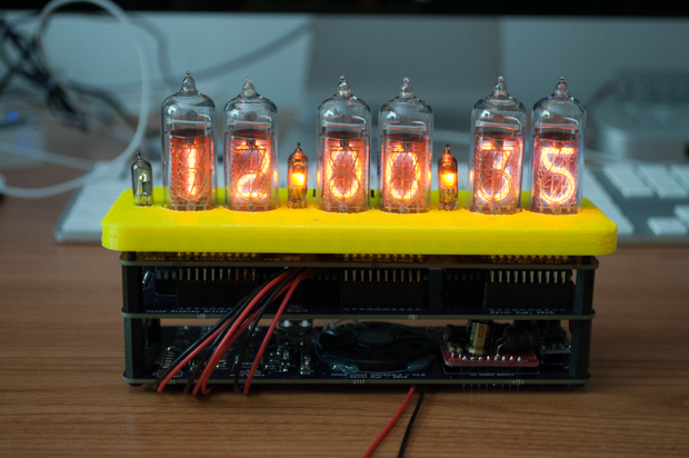
One last test….
Boom. They snap together perfectly.
Now I just need to print the final case in wood PLA and stain it.
See this project from start to finish:
IN-14 Nixie Tubes Nixie Clock V2 - Part I Nixie Clock V2 - Part II
Nixie Clock V2 - Part III Clock Button Panels
