I admit it: I'm a total geek. I love electronics, programming, 3D printing, 3D art, and vintage Apple hardware. I'm always juggling half a dozen projects. I also enjoy documenting it all: my successes, my failures, my experiences... and everything geeky along the way.
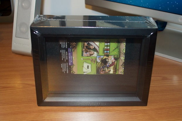
I picked up this shadow box a few weeks ago to use as the enclosure for the Word Clock. The other boxes they had were way too big. This one looked OK, and for $5 bucks, it seemed like a good deal. However, once I started digging into the design a little more, I realized that it was going to be impossible to solder 100 resistors to the back of the LEDS with such limited space. Also, being a rectangle, it’ll look awkward with the words stretched out in a landscape orientation.
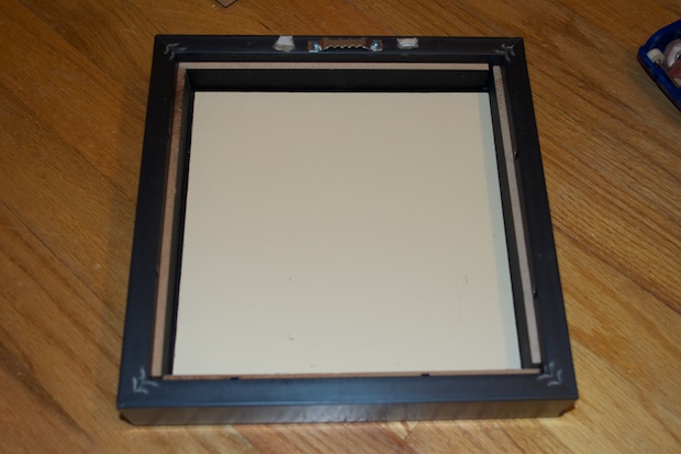
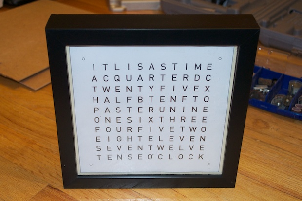
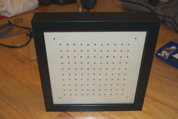
I went back to the craft store to see if they had anything that I missed the last time. As luck would have it, they had one 8” x 8” shadow box for $10. It’s perfect.
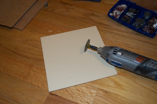
I raided my wooden scraps bag again and found a pressboard backing from an old picture frame. I used my Dremel and cut it to size.
It fits nicely inside the frame and will serve as the board to hold the LEDS.
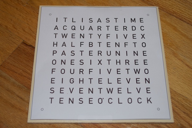
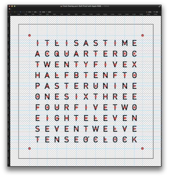
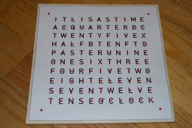
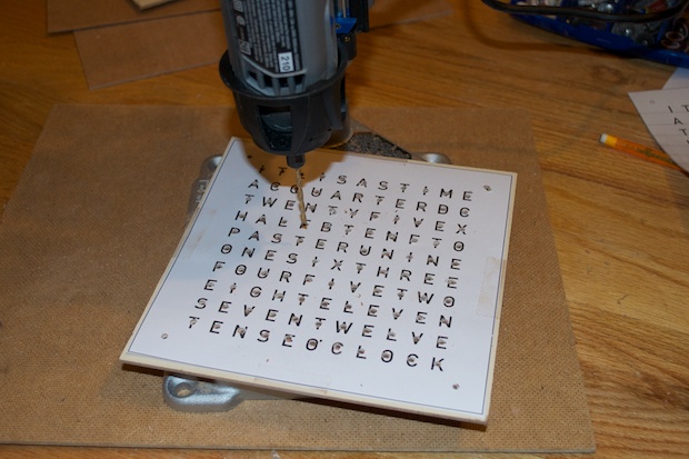
I printed out my overlay template and taped it to the board to get an idea of what it will look like.
Looks awesome.
I then added a drill guide to the overlay so that all the holes would be centered over the letters.
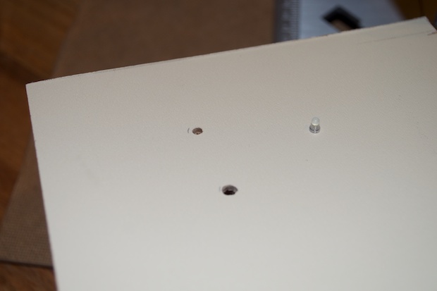
The four holes in the corners will either be for board stands or for LEDs to denote the minute. I haven’t really made up my mind about those yet. The idea is that if the clock says “IT IS QUARTER TO FOUR” and 3 corner LEDs are lit, you know it’s actually 3:48. The more I think about it, the more it doesn’t make sense to have that kind of accuracy. The whole point of the clock is that you’re OK with knowing it’s “TWENTY PAST” the hour. If you wanted to know if it’s really 18 past or 23 past, then you’d look at a “real” clock.
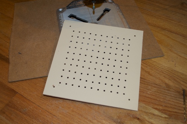
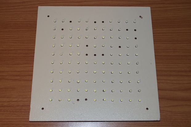
Anyway, it was time to drill the holes. I took a scrap board and experimented with a few different drill sizes until I found the perfect one. I wanted the hole to be big enough to fit the leads, but not for the head to fall through. The idea is that when I bend the leads from the back, the LED head will be snug against the board with no chance of it falling out/through. That way I don’t have to use any glue to hold them in place.
Happy with the drill size, I drilled away.
I don’t know how I survived for so many years without a drill press. The Dremel Workstation made short work of drilling all 114 holes.
Again, just to get an idea. Lookin’ good!
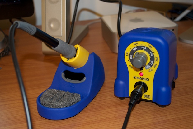
I finally get the chance to try out my new Hakko FX-888.
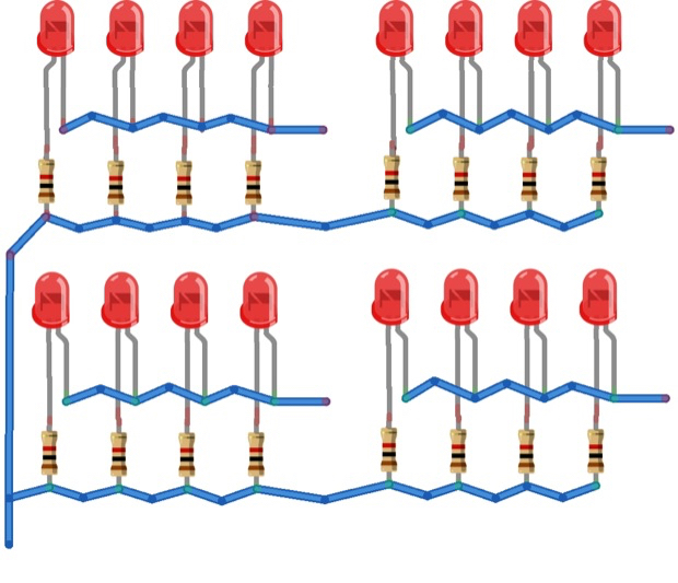
Basically what needs to happen is this:
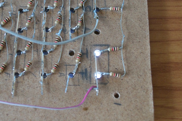
For each word, the cathodes need to be soldered together.
For each word, the anodes need to be soldered to a 1K resistor, then soldered together.
All the anodes for every word also need to be soldered together.
Here’s a graphic to better illustrate the concept:
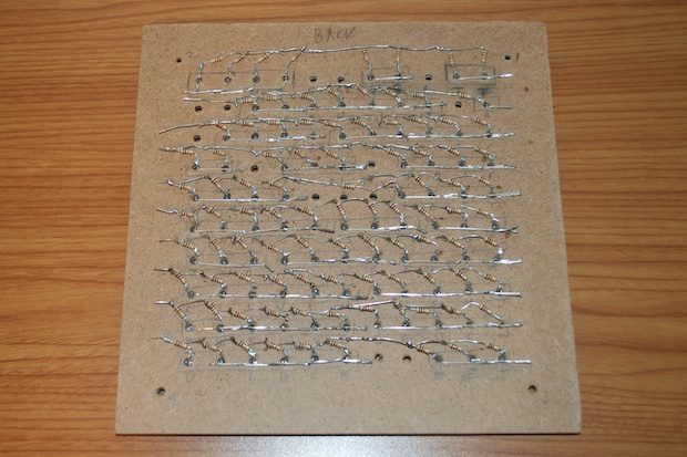
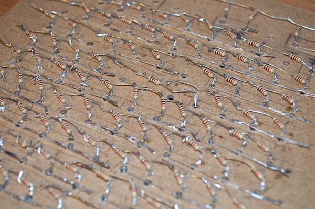
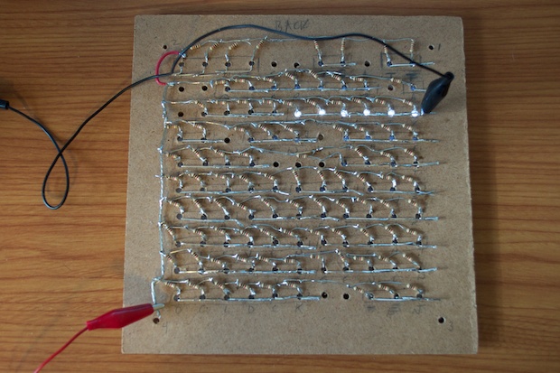
After about 4 hours, all the words were soldered together.
Very tedious work. Heavy metal and coffee helped. The fact that my wife and kids were at a friends house also helped.
I didn’t bother soldering in LEDS to the letters that will never light up. I’ve seen some people go ahead and do it, but you’ll never see them. You could program your sketch to take advantage of the letters and make some sort of startup animation that illuminates them, but I felt it was unnecessary. Besides, I’d need to add one more shift register to pull it off.
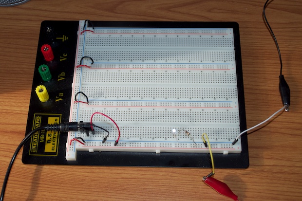
To test the LEDs, I attached a 5V adapter to my bread board and broke out Vcc and GND to a set of alligator clips.
I then connected Vcc to the common anode and connected ground to each of the cathode segments and made sure that each word lit up.
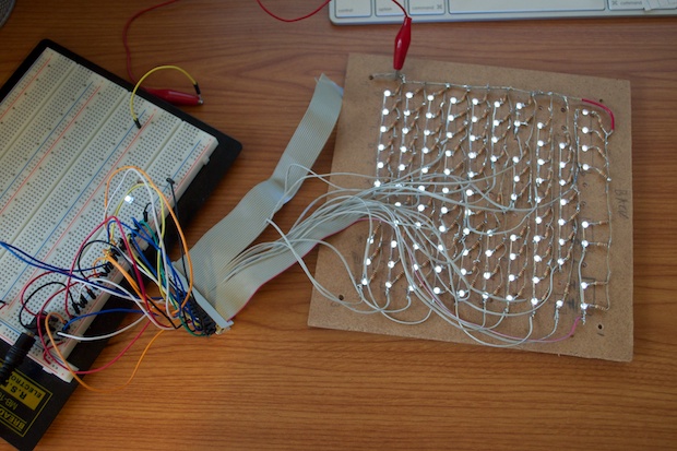
After verifying all my connections were good, I cut up an old IDE cable and started to solder a lead to each cathode segment.
I connected pins from my breadboard to the connector and made sure that I still had a good connection to each cathode segment.
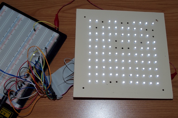
That looks cool! It’s really bright, even with 1K resistors. All together, it about 9 hours to complete the display.
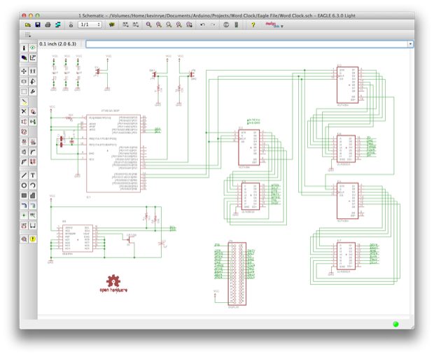
With the display out of the way, it was time to work on the circuit. Here’s the schematic. It’s pretty intense. I based my design a post I saw over at Instrucatables, although mine is heavily modified.
It involves an Atmel 328, 3 x HCF4094 shift registers and 3 x ULN2003A LED Drivers. Of course, I realize that at 620x413, the schematic is unreadable. I’ll post all the source files once the project is complete.
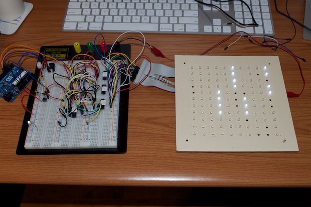
I wired up my circuit and connected the display. I then loaded my sketch.
Boom! It works! “IT IS TEN PAST FIVE”.
The two buttons I added to the circuit increment and decrement the time. I also added a startup sequence. All the LEDs will flash a few times, then the registers will step through each word and light up each one. When the startup sequence is complete, the time is automatically displayed.
Pressing the UP button moves the clock forward. Pressing the DOWN button moves the clock backwards. Pressing them both together displays the startup sequence again.
I’ve seen a few other word clock examples online. Most are basically counting milliseconds as a time base. That’s not very accurate. I know a word clock isn’t supposed to be super-accurate. The display of time is an approximation, but what good is it if the clock says “IT IS QUARTER TO FIVE” when it’s really 4:37? The display of time isn’t precise, but the keeping of timing should be. It’s a clock after all!
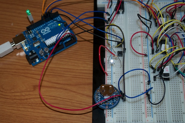
With that said, I decided to use the DS3231 as a time base like I did with my LCD Clock. The DS3231 is a super-accurate real time clock. You’ll need to get your hands on a ChronoDot breakout board since the DS3231 is an SMD chip and won’t fit in your breadboard.
I added the ChronoDot to my circuit and incorporated it into my sketch.
Now you’ll see the clock is set to “IT IS HALF PAST TEN”. I’ll kill power to the clock and then start it back up. After the startup sequence, the time is read back in from the DS3231 and the time is automatically set back to “IT IS HALF PAST TEN”.
I can’t wait to finish up the display and get to work on the board.