I admit it: I'm a total geek. I love electronics, programming, 3D printing, 3D art, and vintage Apple hardware. I'm always juggling half a dozen projects. I also enjoy documenting it all: my successes, my failures, my experiences... and everything geeky along the way.
If you’ve been following along, you know that I picked up a SpeakJet chip about a month ago. It’s a pretty cool chip. It didn’t take long to realize that it would make for a pretty cool R2-D2 project. I even played around with the idea of making a PCB shaped like R2-D2, but the cost was a little prohibitive for what it was. Since OSH Park makes boards in sets of three, I decided to design a board that would not only work for my R2-D2 project, but one that could be used for other projects too.
While I was putting the finishing touches on the PCB design, I gave some thought to what I’d use the other two boards for. I don’t really need 3 boards that make R2-D2 sounds. So what else can I do with them? Maybe a timer? I’m always in need of a timer. I usually tell Siri on my iPhone to set a timer, but maybe I can use the SpeakJet board. Pressing the 3-way navigation switch would announce the timer increment: “5 minutes”, “10 minutes”, etc. Then after the timer went off, it could play a series of sounds and flash the LED. Cool!
I also thought that a talking clock would be awesome. (Me and my clocks! I know.) You could just press the button and the SpeakJet would announce the time. I could set an alarm and it would play some tones and flash the LED. Granted, there’s no RTC chip. I’d need a way to talk to one. Maybe I could keep it simple and just count milliseconds? It might not be super-accurate, but enough so that “It’s half-past five” would be close enough. I’d also need a way to set the clock. I’m sure I could do it with the 3-way navigation switch. After all, I can set my LCD clock with only three buttons. I could have the SpeakJet “talk” you through it. So no display would be necessary. If I did need some extra buttons, it would be nice to be able to add them later.
What about power? How long will the clock run on a 1/2 AA? Maybe I’d like to connect it to an adapter. So any extra Vcc connection would be nice for an adapter or an external battery pack.
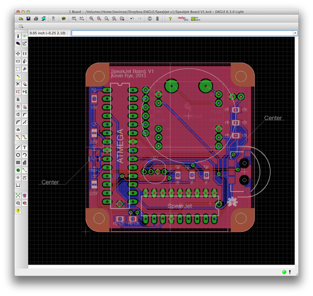
With all that in mind, I broke out pins A0-A5 to a spot on the board that I could add a header to. I could then connect A4 and A5 to a RTC. I could also add some buttons to A0-A3 if need be. I also added an extra Vcc and GND hookup. Whatever I decide to use the other two boards for, it’s nice to know that I can add a little more functionality to them if I need it.
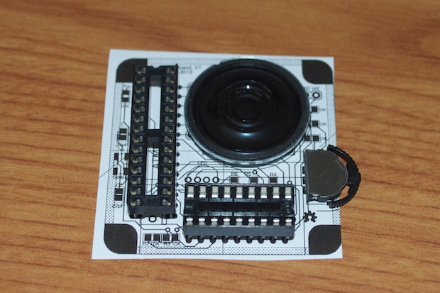
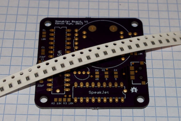
With the design finalized, I printed out the PCB and laid my parts out to make sure that everything fit nicely together.
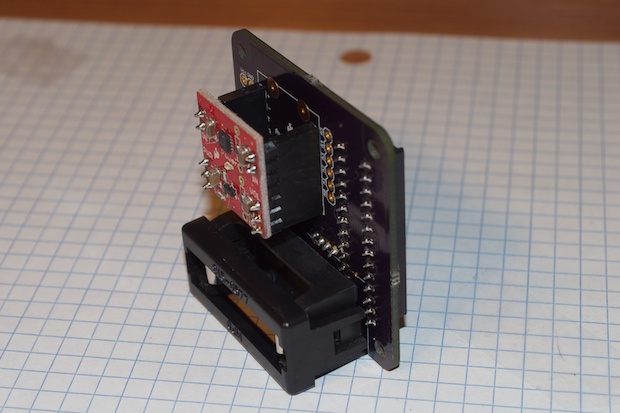
I even made my own footprint for a 1/2AA battery pack as well as incorporated the SparkFun Mono Audio Amp Breakout board as a daughter board.
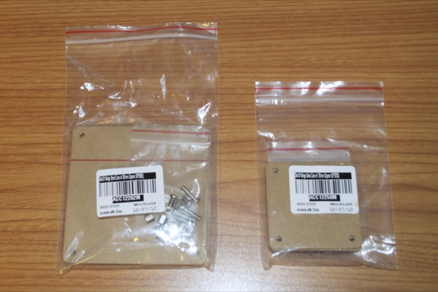
I chose to squeeze the design into the 50mm x 50mm Sick Of Beige footprint from Dangerous Prototypes because I had already ordered a case from Seeed Studio. Since it was coming from China, I wanted to see how long it would take to get one. Actually, I ordered it weeks ago. I had ordered it 10 days before I even had the SpeakJet chip and it still took an additional week to get here. In all, it took 18 days to arrive. That’s good to know. Three weeks for a case can really put a damper on wrapping up a project. It would probably be quicker just getting something laser cut on my own.
I had ordered two sizes. They came complete with screws and stand offs, but they’re way too short to be practical. They’re hardly tall enough to clear anything but SMD parts.
I was originally going to use the 50mm one for a small 7-seg clock. The 80x80 was just in case the 50x50 turned out to be too small. Like I said, I had ordered them weeks before I even had the SpeakJet chip. As nice as they are, what I’d really like is the same 50x50 piece of acrylic, but with a hole cut out for the speaker. Rather than cut a hole in the one I have, I figured I’ll leave it as-is and go ahead a just design the whole thing from scratch and get it laser cut from Ponoko. I’m not going to order any more Sick of Beige cases from Seeed since they take 3 weeks to arrive. For that, I could have just have something laser cut here in the US.
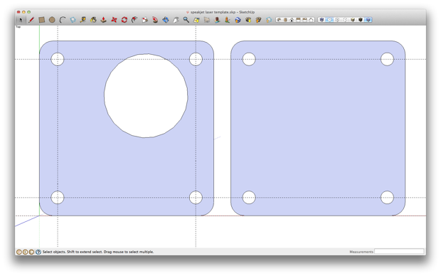
With that, I jumped into SketchUp and put together a 50mm x 50mm design.
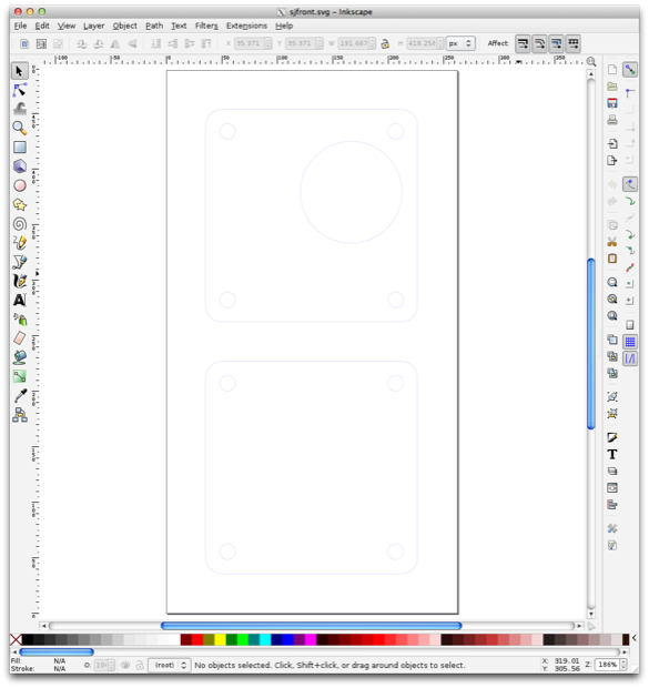
I exported it as an SVG file and uploaded it to Ponoko. With any luck, I’ll have it a few days after the boards arrive.
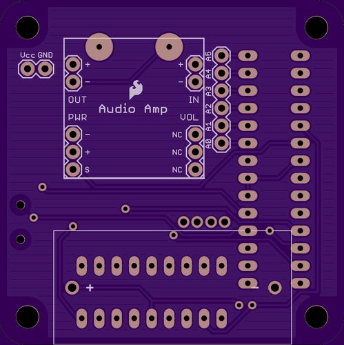
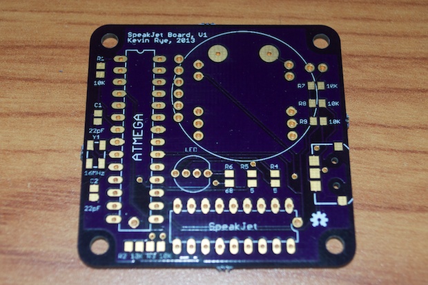
I submitted the PCB a few days before the acrylic, so it arrived first. I’m pretty excited to put it together. This is the first project I’ve worked on that uses SMD components. I’m not counting the LCD clock that used the 16-pin DS3231 RTC. That was just one component, so it really doesn’t count as an “SMD project”.
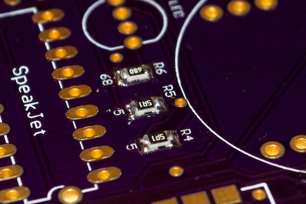
Every capacitor and resistor on my SpeakJet board is a 0805 SMD component; as well as the crystal and the 3-way navigation switch: 13 in all.
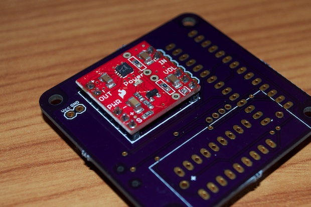
  The SparkFun Mono Audio Amp will just drop in as a daughter board. I would have liked to have just incorporated the parts into my board directly, but there was no way I was going to be able to solder the TPA2005D1 chip with a .65mm pitch. Being my first SMD project, I wanted to keep it semi-simple and not over complicate it. Not to mention, for $7.95, it’s a lot better than anything I could have designed. The last time I tried to make something with an LM386, it didn’t turn out too well. 
OK! Let’s do this! I grabbed my SMD parts and got to it. 
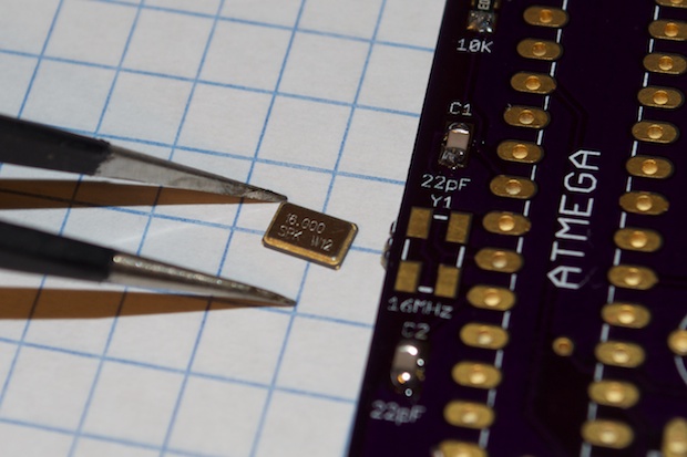
I’m no stranger to SMD parts. I’ve been admiring them for years! I’ve stared at (and admired) a countless number of computer logicboards and have always dreamed of the day that I’d make the jump. I didn’t realize until I actually held one with a pair of tweezers just how small they really are. They are tiny!
I'm glad I went with the 0805 size. I was considering using the next size down, 0603, so I could make super-small thing-a-ma-jigs. I'm glad I didn't. I searched online and although the general consensus seems to be that 0603s are "doable" by hand, I don't see how you can solder them by hand after holding and 0805 part.
1206, 0805, and 0603 seem to be the most common sizes. You can go down to 0402, but then you most likely need a pick and place machine and you’ll have to wave-soldering them. I've seen guys online apply solder paste to the pads with a toothpick, place the parts with tweezers, and then bake the board in an oven. That seems like more trouble than it's worth. I don’t think my wife would be a big fan of me cooking electronics in the over either.
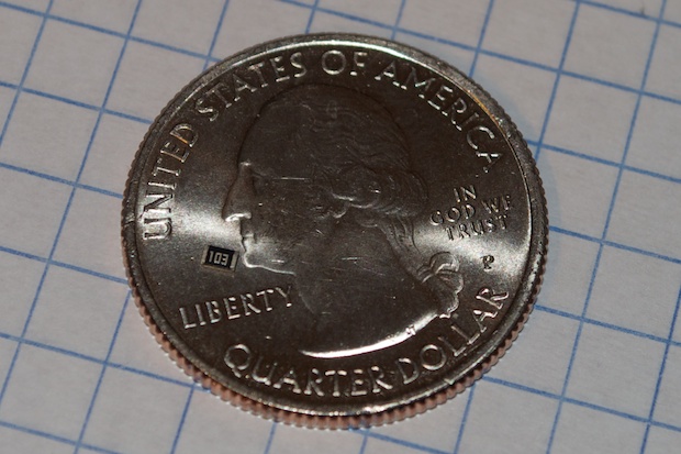
Just to put things into perspective, here’s an 0805 resistor sitting on a quarter:
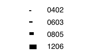
Now look how the 0805 compares to 1206, 0603 and 0402:

Not happening! I figured 0805 was the "sweet spot". They're tricky, but with some practice I'm sure I'll be a SMD ninja in no time!
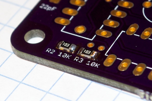
To solder them, I added solder to one pad, placed the component and remelted the solder. That let me wiggle the component into position. When I was happy with its placement, I lifted the iron and let the solder cool. Now it’s straight and flush. All I had to do then was apply a little solder to the other pad and it was done.
I repeated the process for all the other component. It’s tricky stuff, but I think I’m getting the hang of it. 
After the resistors and capacitors were done, it was time to tackle the crystal. This one looks a little tricky. 
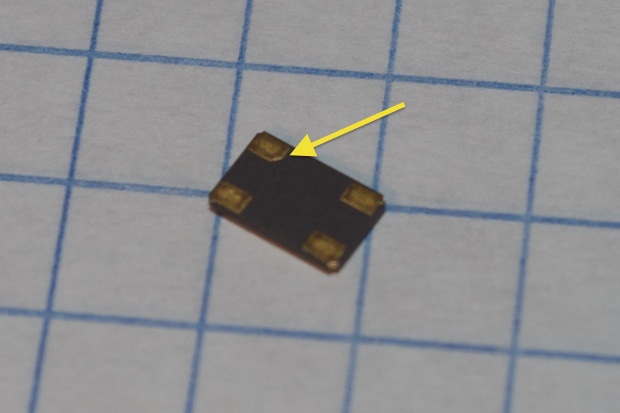
The pads are on the bottom. One of them is notched to let you know which pin is pin 1. Not that it matters. The crystal internally is at a diagonal. So either way you orient it, each end of the crystal is in positions 1 and 3. The keying I guess is more important for when you’re laying out the circuit; so you don’t connect your capacitors to the wrong pads. Pins 2 and 4 do not have an internal connection, just to the case. 
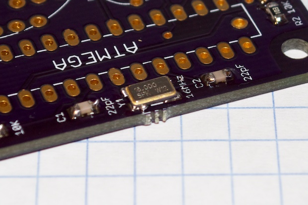
It was a little tricky since the pads were underneath. I opted to apply a small amount of solder to each pad, place the crystal in place, and then reheat the pads from the edges. Once one end is soldered into position, it’s impossible to move the other end. The crystal slid to the side just a hair and it was no longer centered on the pads.
I fired up my hair-air rework station and tried to reheat all 4 pads simultaneously while nudging it into position with my tweezers. Success! 
It’s pretty well-centered. I just hope that the fact that I soldered each pad, and then reheated the whole thing with the hot air didn’t cause any damage. The datasheet calls out a max solder temperature of 260°C for 10 seconds. I had my station set to 250, and I tried to limit the exposure as much as I could. So I don’t think I killed it, but my fingers are crossed nonetheless.
The last SMD part to go in was the nav switch. Again, the pads are underneath. I chose not to apply solder to the pads like the crystal. Instead, I just held it in place with some tape and soldered the pads head-on. I then passed some hot air over it as I gave it a little wiggle to help the solder flow under the pads. It seemed to work, because it feels like it’s held in pretty securely.

That does it for the SMD parts. Pretty tricky stuff, but I’m getting the hang of it. After a little trial and error, I’ve definitely decided that adding the solder to every pad first isn’t the proper approach when using an iron. It’s definitely better to do one at a time. Only apply to all the pads of a component when using hot air.
I only planned on assembling one of these, but I might go ahead and assemble the other two boards just for the practice.
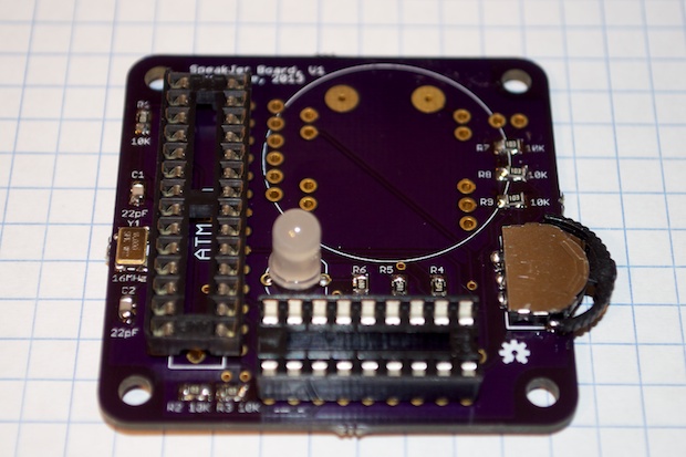
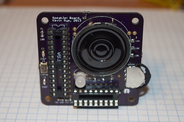
With the SMD parts complete, I went ahead and added the DIPs and the LED.
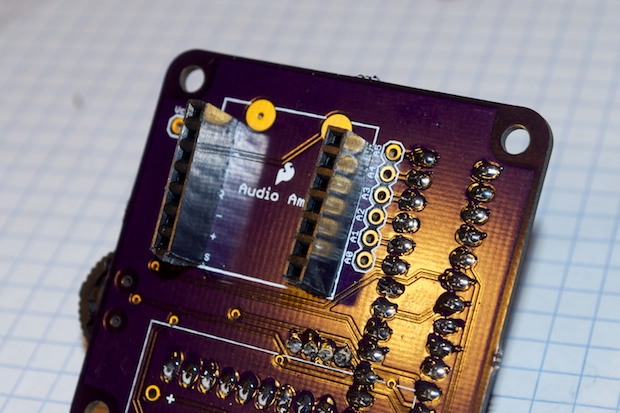
 It sure would be a shame to go through all this, add the $8 mono amp, and find out that my design doesn’t work. I’d hate to waste a perfectly good breakout board. Once I solder the speaker to the front, it’ll make it that much more difficult to remove the amplifier. With that in mind, I opted to solder in some female headers so I can easily remove the amplifier if I need to.
They sit a little higher from the board that I would have liked, but it doesn’t matter much considering the amplifier won’t sit any higher than the battery pack for the 1/2AA. So it’s not going to make the overall size any bigger than it’s already going to be.
So if this whole thing proves to be a huge waste of time and money, at least I can salvage the amplifier without having to unsolder the whole thing.
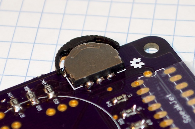
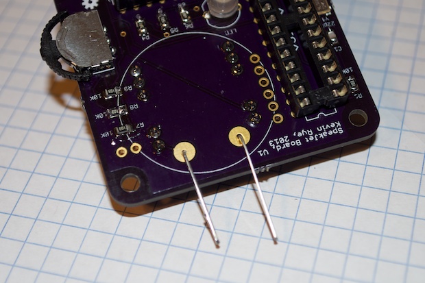
Last up is the speaker. Since the speaker only has solder pads and no through holes for wires, I soldered some discarded resistor leads into the holes on my board. I then bent them over and cut them down to serve as contacts.

I then soldered my homebrew contacts to the pads on the back of the speaker and held the speaker in place with a small dab of hot glue.
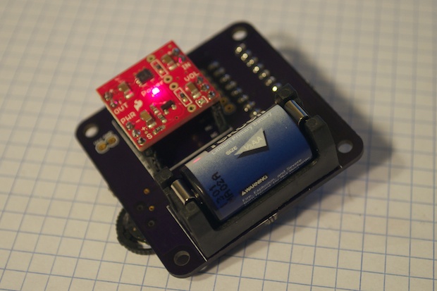
 With the assembly complete, it was time to see if it worked. I popped in the battery and the amplifier came to life. Cool! No shorts! I wanted to power it up without the chips first to make sure, at minimum, that Vcc and ground were correct. I’d hate to nuke my $25 SpeakJet chip.

So far so good. I modified the blink sketch to flash the red pin of my RGB LED and loaded the sketch onto my ATmega328.
Sweet! I didn’t damage the crystal. Everything looks like it works. All that remains is to install the SpeakJet chip and try it out. I loaded my sketch onto the ATmega328 and installed the SpeakJet chip.
Success! It works like a charm.
You’ve probably noticed there’s no on/off switch. The nav switch is the “on” switch. Pressing the nav switch tells the ATmega328 to wake up the amp. The ATmeg328 will then shut down the amp after the audio has played. Eventually I’ll tweak the code to also have the ATmega enter low power/sleep mode.
This was a really fun project. Come to think of it, it’s better than the SoundBox ever was… and it talks!
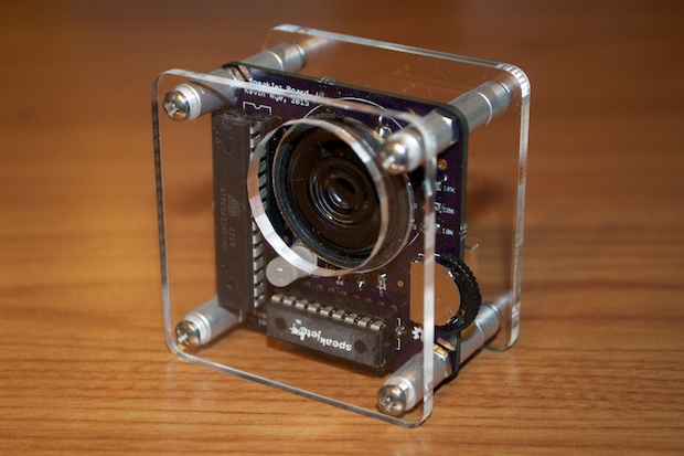
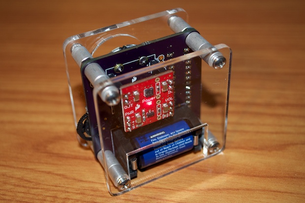
5/24 UPDATE: The acrylic that I had laser cut from Ponoko came in. It came out really good. The hole on the back is just the right size to allow easy battery access.