I’d like to try my hand and making a
Tesseract. I love all the Marvel movies, as well as my kids. So I think they’ll get a kick out of seeing one on my desk.
I’ve seen a few examples online that have been made by others and they’re basically a few blue LEDs in a box connected to a battery and a switch. I can do much better than that. I’d like to at least animate the LEDs.
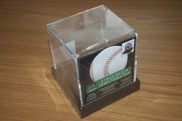
I swung by the craft store on the way home from work and picked up a $10 dollar acrylic baseball case.
Knowing how much real estate I had to work with, I set about designing a PCB that would hold several blue and white LEDS.
I’d like the cube to have white and blue LEDs on all sides and have them all pulse in and out randomly using PWM. Since an ATmega 328 only has 6 PWM channels, I won’t be able to address all 45 LEDs individually without some extra hardware. I’d could just use a bunch of
NeoPixels, but I don’t want to spend $30 bucks on LEDs and then another $30 bucks on PCBs. I’m sure it’ll be really cool, but I really don’t want to spend that kind of money on a desk prop. I’d like to use as much stuff that I already have as I can. For instance, I don’t want to design another PCB with an ATmega and some LED drivers. I want to just use one of my $5 dollar
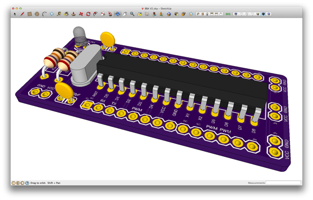
Bare Bones Arduino PCBs. I don’t want to buy any more LEDs, since I’m sure the leftover
RGB LEDs I bought off eBay will be fine. I bought 100 for $13 bucks. SparkFun charges almost a dollar a piece, so I think I’ll just clip the leads off and use them as blue LEDs. I have a ton of leftover white LEDs from the
Word Clock too. The only thing I really have to buy are PCBs for the LEDs.
I plan to connect 5 PCBs together to form a cube, leaving the bottom open for the Bare Bones Arduino. Each side will have 5 blue LEDs and 4 white LEDs. Each color will be on their own PWN channel. I can then drive the white and blue LEDs independently of each other. Since I only have 6 PWM channels, I’ll have to cascade a few sides together.
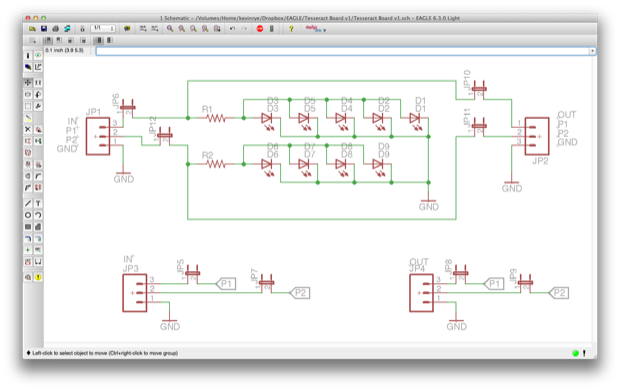
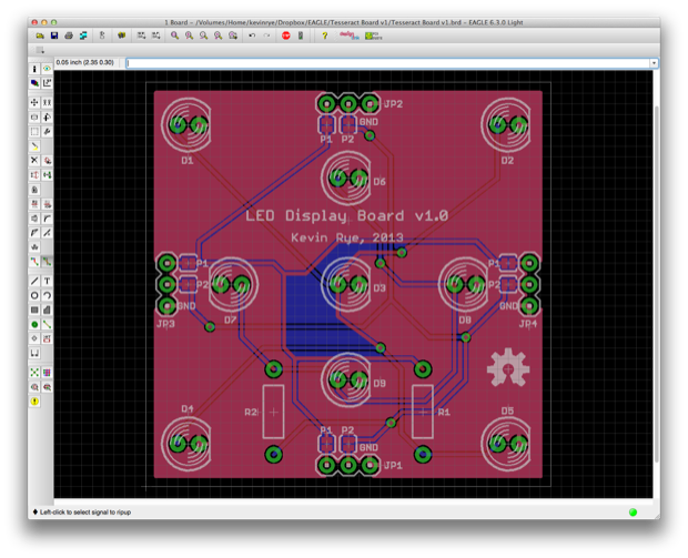
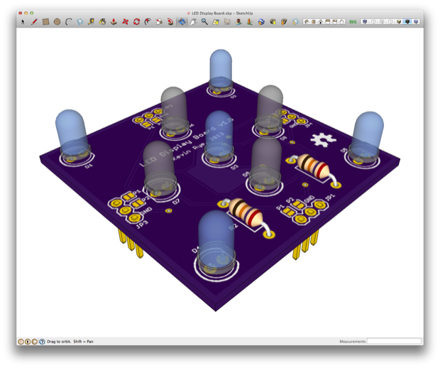
Here’s what I came up with. It’s a square PCB measuring only 1.9” x 1.9”. The corner and center LEDs are blue; the rest are white. The headers have two functions. First, they simply serve as a means to connect the sides together. Second, I included some SMD jumper pads so that shorting them will cascade the white and blue PWM channels, as well as ground to the adjacent side. All the inputs/outputs are connected together. I can connect any one of them to the Bare Bones Arduino and the signal will carry to all four headers. If I then want that signal to carry out to an adjacent side, I just short the jumper to that side.
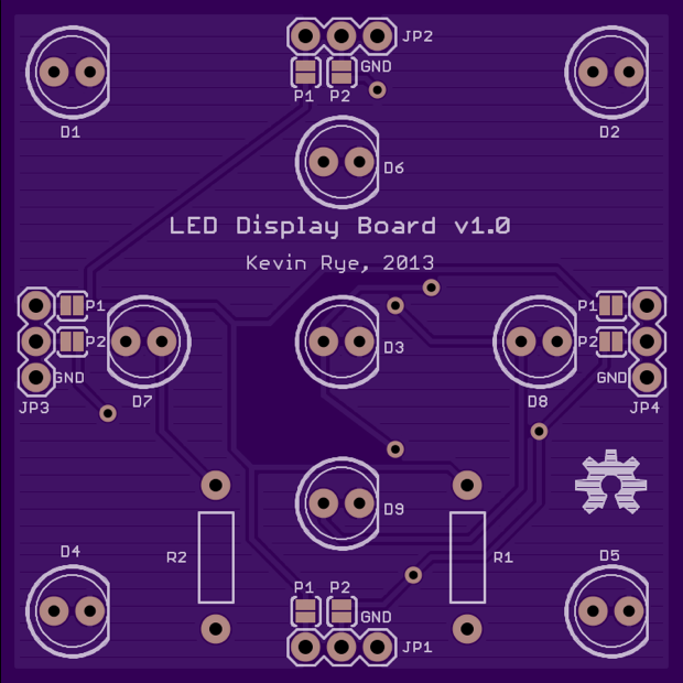
Here’s the OSH Park render. I was going to call it “The Tesseract”, and plaster it with some cool Marvel graphics, but since I’m ordered 6 PCBs and only using 5, I’ll have one left over. I might throw that extra board into something else and fill it will red and yellow LEDs and make some kind of fire thing. So it won’t be much of a Tesseract. That, and I’m open sourcing the design, so if someone’s going to use the PCBs for something else, it would look rather silly with “The Tesseract” all over them. I figured I’d just make it generic and it could be used for anything that needs a bunch of LEDs.
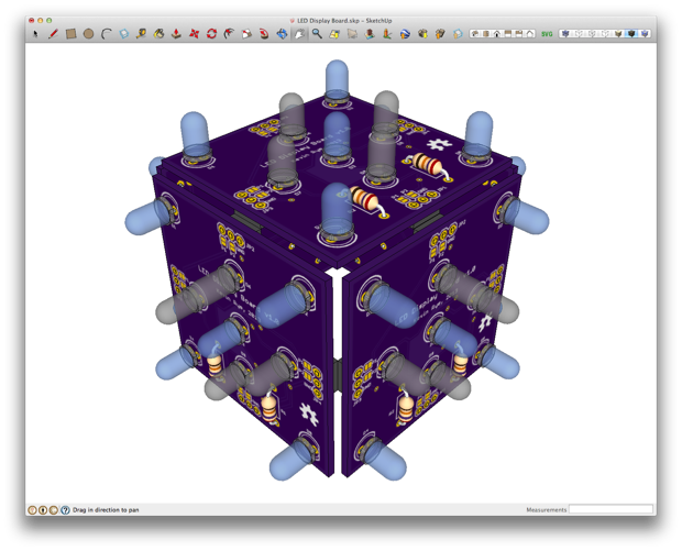
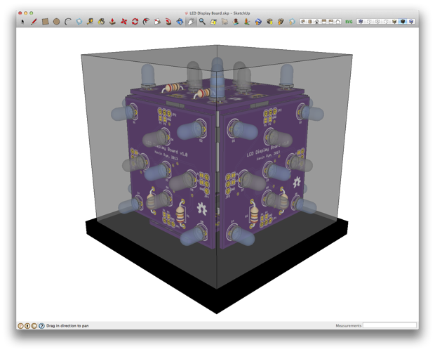
I then chalked up a 3D model to do a little reality-check in regards to being able to connect a bunch of them together into a cube.
I’ll connect the sides together with right-angle headers. It should work.
I then just have to mount it on top of one of my Bare Bones Arduino boards.
I didn’t include any additional holes for board stands, so I might just secure the LED PCBs to the Bare Bones PCB with 2 drops of hot glue.
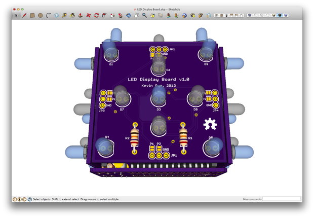
Same goes for securing it to the bottom of the enclosure. I’m going to spray the inside of the display with some white paint, so it doesn’t need to look super-pretty on the inside.
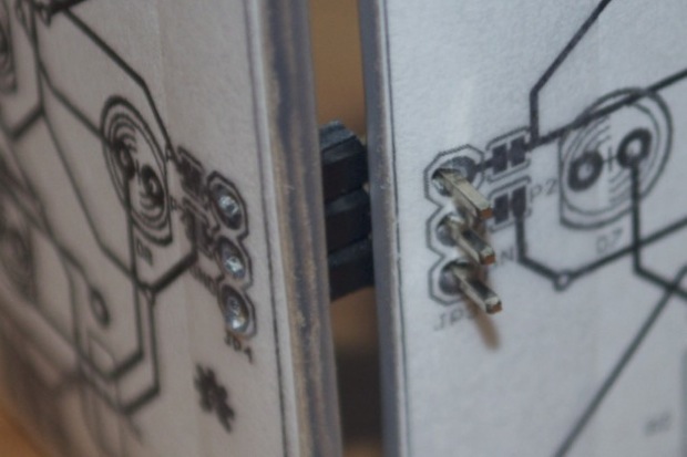
As an additional reality-check, I printed out the PCB and taped a few copies to some cardboard. I then checked to make sure that my right-angle headers were long enough to secure 2 sides together. Again, looks doable.
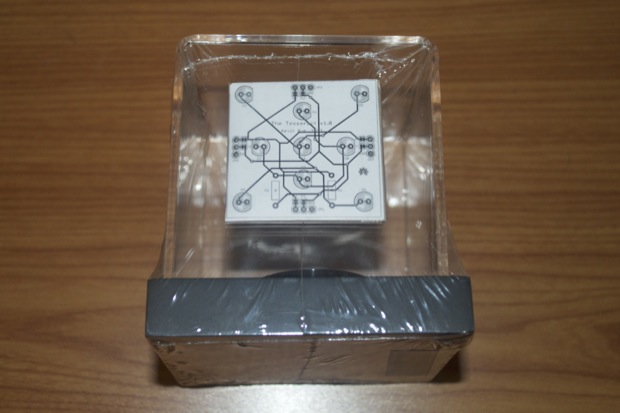
The PCBs are definitely small enough that the whole thing will fit comfortably within the enclosure. I’ll just have to drill a hole into the bottom to feed in a cable for power.
I already placed the order for my PCBs, so hopefully I’ll be putting this guy together next week!
See this project from start to finish:
The Tesseract
The Tesseract Build, Part I The Tesseract Build, Part II
