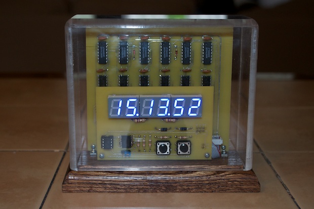
This is the
first clock that I ever made. I made it in 2001, long before the open source community exploded. Long before Arduino.
There’s no microcontroller. It’s all straight-up TTL. I used a bunch of 7490 decade counters to divide the 60 Hz line signal down to 1Hz. The 1Hz signal is what the clock counts as a timebase. The count basically cascades through the various seconds, minutes, and hours sections.
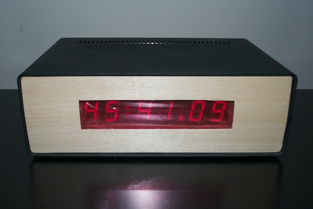
I really wanted to have a go at making a nixie clock like my Dad did in the 70s, but I was apprehensive in dealing with the high voltage required for nixies. I settled for 7-segment LEDs instead.
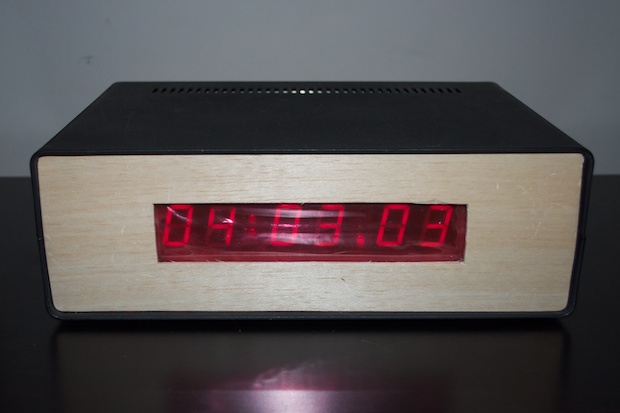
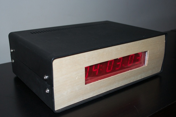
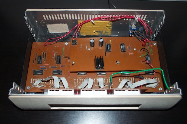
As far as a case, I didn’t have any tools at my disposal for making one. There was no way to have something laser cut back in those days. Not on the cheap anyway. I settled for an old beat up project box that I found in the garbage at work. It’s way bigger than it needs to be. I spray painted it black and made front and back panels from balsa wood. I didn’t have a Dremel back then, so I was limited to materials that I could cut with a box cutter.
As if it wasn’t homebrew enough, I didn’t even have any red plastic for the display. I took a clear piece of plastic and wrapped it in red plastic foil. (The kind of stuff they wrap Easter baskets in.) No joke.
As far as the back, I included a jack for the adapter, a reset switch, and two toggle switches to set the time.
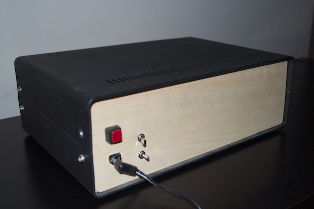
Setting the time is brutally slow. Using the switches, I basically redirect the 1 Hz signal into either the minutes or hours sections in order to set them.
Back in 2001, it wasn’t easy for the do-it-yourselfer to have a PCB made. Small batch fab houses like OSH Park didn’t exist. If they did, I sure didn’t know about them. In any case, I’m sure the setup fees and cost kept it out of reach for the simple hobbyist.
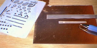
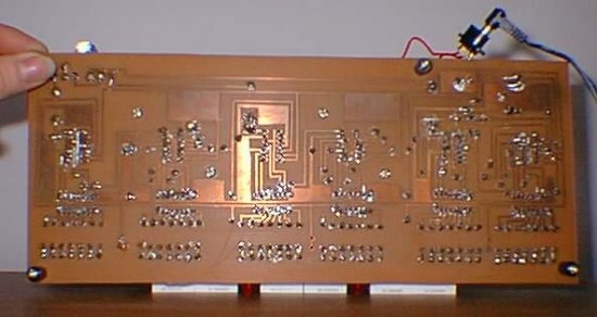
I basically had to etch my own board by hand. I ordered a large 12” x 12” copper board from Jameco along with some PCB etchant solution from Radio Shack. All the copper for the traces were masked off with pieces of tape cut out with an X-Acto knife, as well as a Shaprie marker.
Please excuse the tiny low res images, but in 2001 all I had was an Epson Photo PC camera from 1995 that took images at 640x480.
You do what you can with what you have. All things considered, the clock came out pretty good. For the most part, it works. I was pretty happy that I figured out how to make one. I never had a schematic. I just researched how decade counters worked, how you can configure them to divide by 2 and by 6, and figured out how to make them into a clock.
With the popularity of iPhones and iPads, the internet nowadays is part of our daily lives. It’s so ingrained into everything we do, it’s hard to believe that in 2001 there was nothing on the internet about how to configure a bunch of 7490s to count to 23 and go back to 00. We’ve grown so accustomed to having everything at our finger tips that it’s hard to remember a time when we had to go to the library to look something up. I actually took books out from the library on TTL chips and researched it.
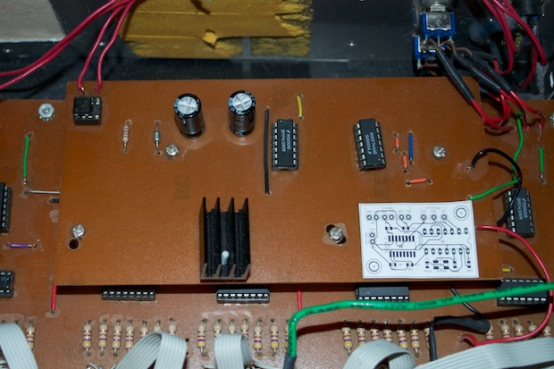
The clock is powered by a 9V AC to AC adapter. I wouldn’t have to deal with mains voltage, but I’d still have access to the 60 Hz line signal. The daughterboard takes the 60Hz from the line and divides it down to 1Hz. The bridge rectifier converts the AC to DC. The 7508 voltage regulator then knocks the 9 volts down to 5 volts, requiring a heatsink. Again, way bigger than it needs to be since all the traces were done by hand.
Although the clock does what a clock does, it is very susceptible to noise. I didn’t know to put filter caps across the 7490s, so the clock does have a tendency to bug-out when there’s noise across the line. It’ll be ticking along fine for days, then all of a sudden, it’s 97:30 o’clock. Annoying. It then takes a few minutes to set the hours and minutes with the slow 1 Hz signal.
I eventually got fed up constantly having to reset it that I threw it in the closet. I swore one day I’d fix it or make a better one. It wasn’t until 2007 that I decided to
improve the design and start from scratch. Once I found out about ExpressPCB, I decided it was time to design and have a professional PCB made.
The “do-over” came out amazing. It’s extremely accurate and runs like a top. There were some hiccups and set backs, but
I eventually completed it.
Even though I’ve been taking things apart and tinkering with electronics since I was a little kid, I don’t think I ever made anything beyond that of the occasional blinky light with some transistors, or a little sound box with a 555 timer. Everything that I made was basically stuff from those old
Forrest Mims books that I bought from Radio Shack. The 7490 clock was the first “big thing” that I ever designed and made from scratch.
Despite looking like a prototype, as well as a total piece of junk, I’m still very proud of that first clock. It’s a shame to leave it just sitting in the closet. After 13 years, I think it’s time to finally get it up and running the way it should, give it some upgrades, and a new enclosure.
I got version 2 of the 7490 clock running like a champ with the aid of a DS3231 RTC chip. I used an ATtiny85 to configure the DS3231 to run at 1Hz. It’s extremely accurate. So it seems like the obvious choice of a timebases for this clock too. I’m going to ditch the 60Hz line signal in favor of the DS3231. Just like version 2, the addition of an ATtiny will also allow me to easily implement fast and slow setting for the minutes and hours.
I’ll be able to ditch the entire daughterboard completely. No more bridge rectifier. No more 7850 regulator and heatsink.
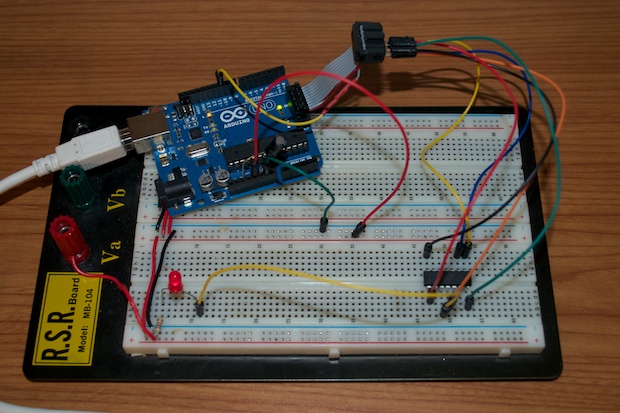
I modified my original sketch to work with the ATTiny84. I configured my Uno as an ISP and connected my homebrew ICSP cable to my breadboarded ATTiny84. I then connected an LED for the blink sketch.
The bootloader took without a problem, and the blink sketch uploaded fine.
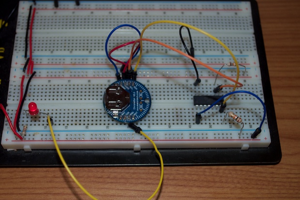
I connected my DS3231 breakout and uploaded my sketch. It works!
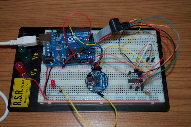
I removed my Arduino and tried the circuit standalone. It works. At power-up, the ATTiny configures the DS3231's SQW pin to output a 1 Hz signal. Since it does it at power-up, there's no reason to add a battery backup to the DS3231. So I can save a little space on the PCB by not having to include a battery.
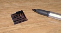
With the ATTiny squared away and the circuit validated, it was time to put together a PCB. I hopped into Eagle and designed a new daughterboard. It has inputs for the power adapter, set switches, and outputs for the seconds, minutes, and hours sections.
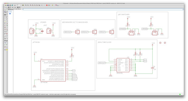
The board is tiny compared to the old one.
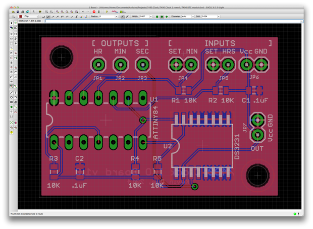
Orders of magnitude smaller. It measures ~1 5/8” x 1 1/16”.
Getting 3 PCBs made by OSH Park only cost $8.90. Being a simple I/O board, I’m sure the other 2 PCBs will come in handy for other protects too. Even if it’s just blinking some RGB LEDs.
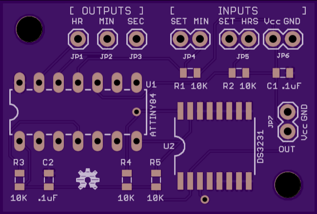
I can’t wait for the PCBs to come in. In the meantime, I can get to work on designing a much smaller laser-cut enclosure.
See this project from start to finish: Digital Clock 1.0 Upgrading My Old 7490 Clock, Part I
Upgrading My Old 7490 Clock, Part II Upgrading My Old 7490 Clock, Part III Upgrading My Old 7490 Clock, Part IV Upgrading My Old 7490 Clock, Part V
