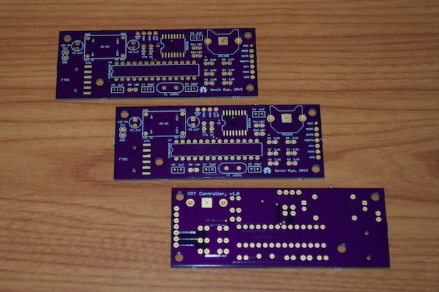
OSH Park broke a record this time. They had my boards back in 8 days! Amazing. I thought I had another week to work on some code. I guess not. I'll just have to jump right into the build! Not that I mind.
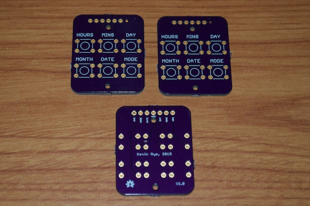
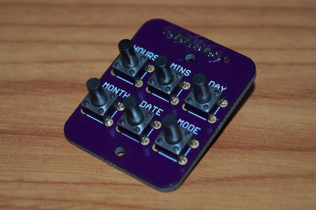
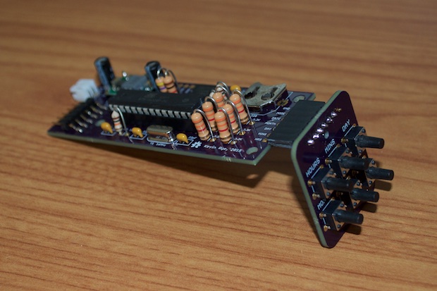
The button board was a snap. Just 6 buttons and a header.
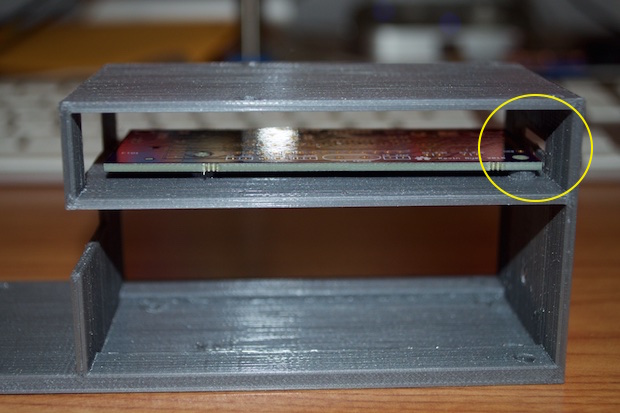
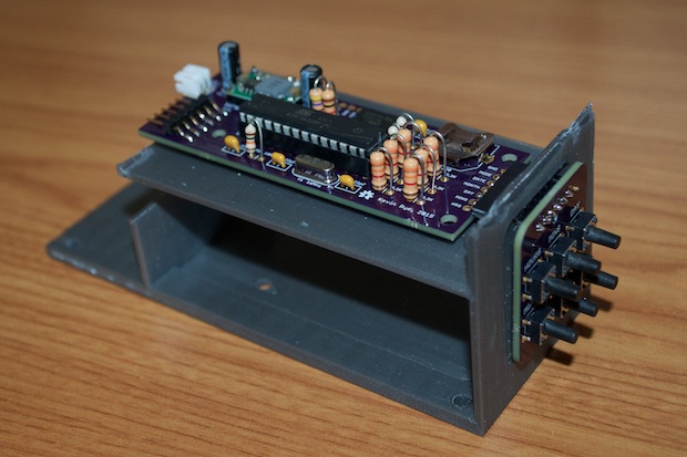
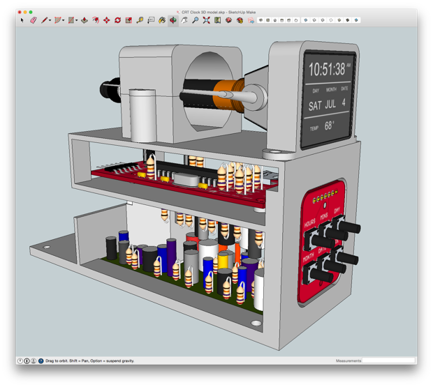
Just as a test, I laid one of the controller board PCBs into my 3D-printed frame just for a sanity check. I was nervous that I didn't give the front header enough clearance. As I suspected, it's way too tight to get a right angle header in there. I'll have to tweak the model.
In the meantime, I figured I'd go ahead with the build. I won't know for sure exactly how much space I'll need until everything is soldered together and assembled. I first need to put everything together in order to see if I need to make any last minute tweaks.
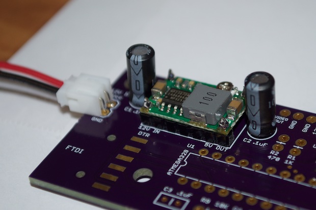
I started with the power stuff and dialed the voltage-out on the converter to 5V before soldering anything else in.
Once that was good to go, I went ahead and soldered in all the necessary components for the ATmega328 and the DS3231 RTC. I then uploaded a blink sketch to make sure that it worked. All systems go. I then uploaded my
preliminary TVout sketch.
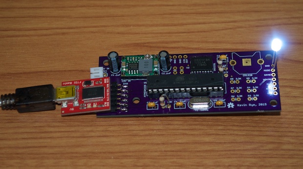
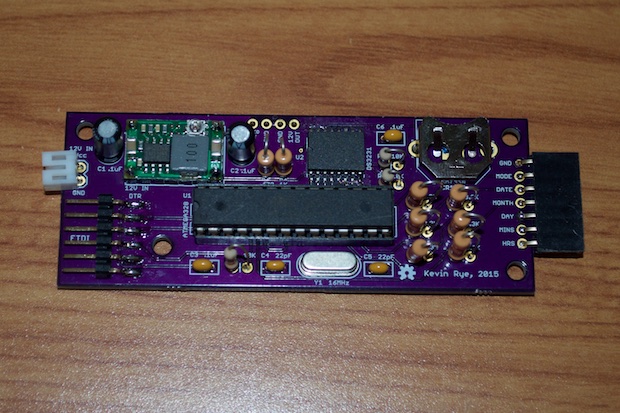
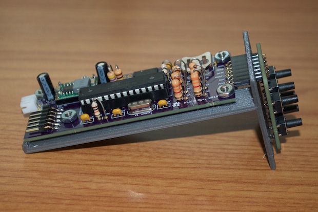
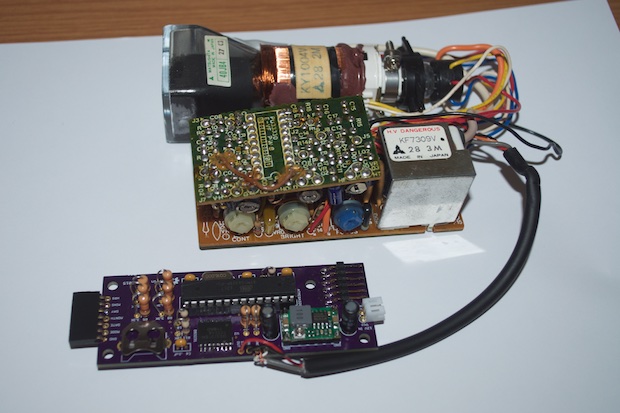
It was then just a matter or soldering in the resistors for the set buttons, the header, and the battery backup. This board looks really cool. If I used all SMD-components, I probably could have made this PCB half the size, but I intentionally used as many through-hole components as I could in order to match the vintage look and feel of the old CRT PCBs.
I then clipped the two PCBs together. Looks good.
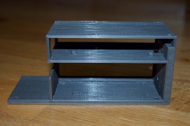
I then chopped the top off my prototype frame in order to take a few measurements. As I suspected, the PCB and mounting holes need to be moved back a good 5 mm.
In order to save myself several hours, as well as material, I only printed the portion of the frame that I needed in order to verify that I nailed the dimensions.
I then dropped it into MatterControl and printed it out. It's perfect.
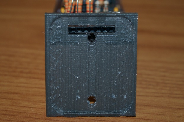
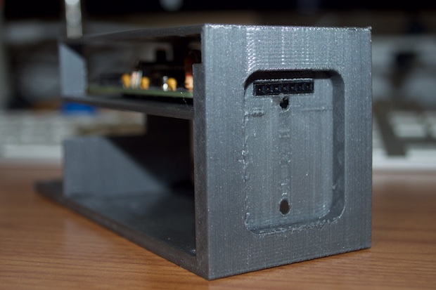
The header fits nice and snug within the cutout.
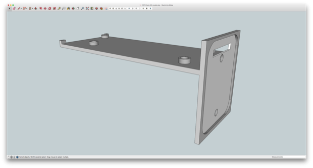
I then updated my model with the new changes and put it all back together for one last look. Solid.
About 7 hours later, I had the final version.
Perfect.
It was time to install all the electronics. I started by soldering in the CRT connections.
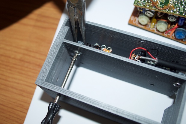
I then mounted my controller PCB. It was a lot easier to do than I had imagined. Thankfully, I realized early on in the design that I'd need to put holes in the bottom of the frame so that I could get a screwdriver under the screw heads. All I needed to do was hold the nuts in place with a pair or pliers.
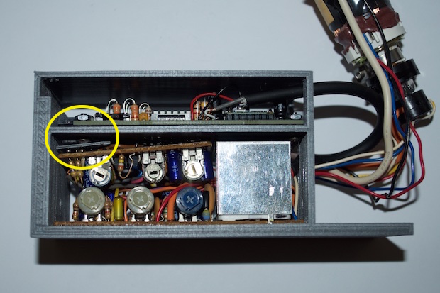
One thing that I didn't anticipate was that two of the screw heads might touch some of the components on the underside of the CRT PCB. I put in a few millimeters of clearance to stop that from happening, but it still looks a little too close for comfort. For now, I just slid a piece of scrap PLA in there to shield the PCB from the screw heads. When I'm all done with it, I'll just put a small sliver of black tape in there; something that won't be as visible.
Once the controller board was installed, I secured the CRT to the top with my custom pieces. I then attached the button board to the front.
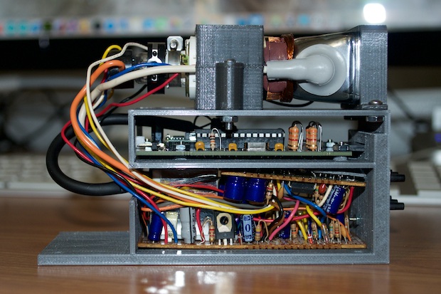
It came out awesome.
The last thing to do was solder a barrel jack to the power connector. Once I put it in a case, I'll incorporate an on/off switch.
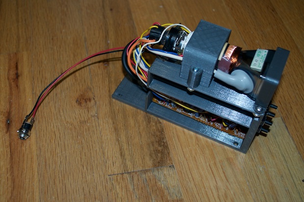
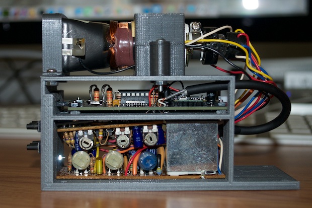
I plugged in my 12V adapter and crossed my fingers. A few seconds later, the CRT started to glow and my clock display came on screen. Awesome! I love it when everything just comes together at the end and it just works. No hacks, no head scratching, no second spins. It just works.
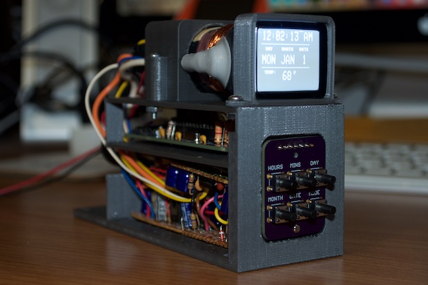
Although the data on screen is being pulled in from the DS3231, the code for the set buttons has not been written. I need to wrap that up and tweak the display to better center everything. I also want to put in some kind of on-the-hour animation to limit screen burn. I also have to design the laser-cut acrylic case of it.
This project involved some serious engineering, and I'm really happy with the way that it's coming out.
See this project from start to finish: CRT Clock, Part I CRT Clock, Part II CRT Clock, Part III CRT Clock, Part IV
CRT Clock Case
