While digging through some old paperwork looking for an old receipt, I happened to find an old schematic that my Dad chalked up for me as a kid. We were at my Grandmother's house and I was board out of my skull. My Dad had to swing by work to "check the faxes" and offered to have me tag along. He worked for a big electronics company, so I used to love visiting the labs on the weekend when no one was there. I got to rummage through the scrap heaps and grab cool looking miscellaneous parts. My Dad grabbed a few caps, resistors, and transistors, checked the faxes, and we headed back to Grandma's house.
When we got back, he chalked up this schematic for me and told me to have at it. My Dad always had a soldering iron and toolkit in his briefcase, so I got to use his tools. That was almost 30 years ago because I don't think I was much older than 10. I don't remember if he told me what it did or if it was more of a "build it and see what happens" kind of thing.
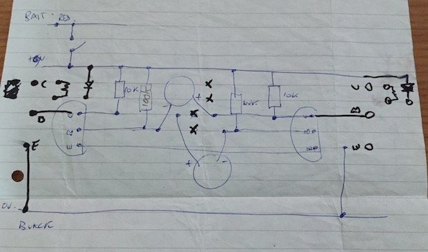
I do remember building it, and I remember it working. I never made anything with transistors before, so this was pretty exciting. I used to mess round with 555 timers and make little buzzers and other little nick nacks from the Forrest Mims books you'd find in Radio Shack. I still have them after all these years.
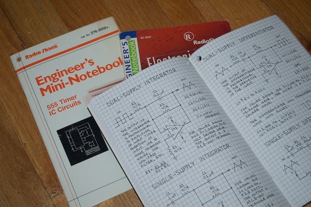
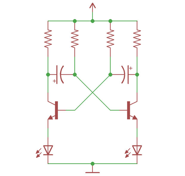
Finding this schematic for an astable multivibrator made me want to build one again for old times' sake.
I took the liberty of cleaning up the schematic in Eagle. It's nothing fancy. If you Google for it, you'll find a million different variations. I could go into RC time constants and the theory of operation, but I'll leave that as an exercise for the reader. For now, I just want to build one!
I grabbed some components from my parts bins: 10K and 100K resistors, 10uF caps, 3904 transistors, and LEDs. If you don't have these components just lying around, then electronics is not your hobby!
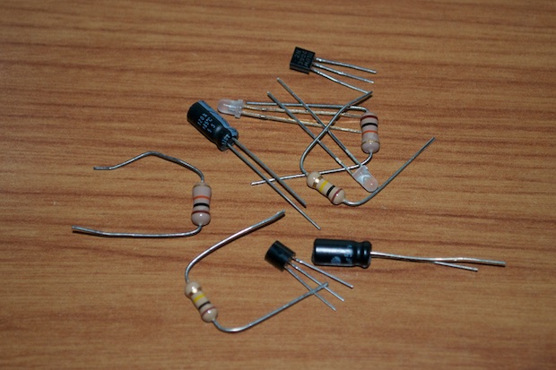
Just to make sure everything worked, I threw them onto my breadboard and applied 5 volts. Voilà!
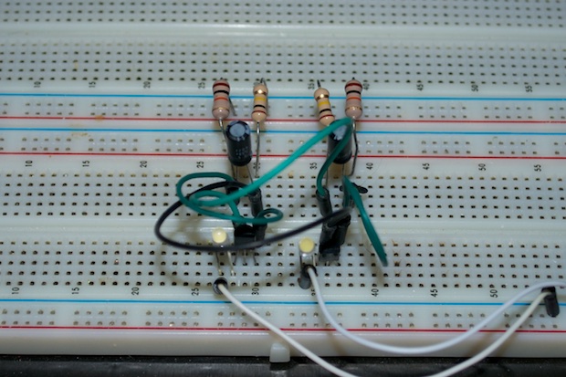
Here it is in action. I know it's nothing to write home about, but it's fun to see it go. It's cool to see what appears to be a bunch of components haphazardly soldered together do something!
I was tempted to solder it onto a small perfboard. I have tons of them, but I thought it would be cool to solder all the components together exactly like the schematic. It'll make for a cool little desk prop at work. Who knows, maybe it'll look like a little piece of art.
I think that's as close as it gets!
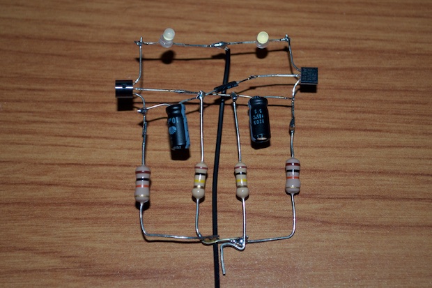
I then soldered it directly to a 3.6V 1/2AA battery holder. It's just the right size to double as a stand. I'm not going to bother with a switch. I'll just pop the battery in when I want to run it.
I popped in the battery and it was good to go.
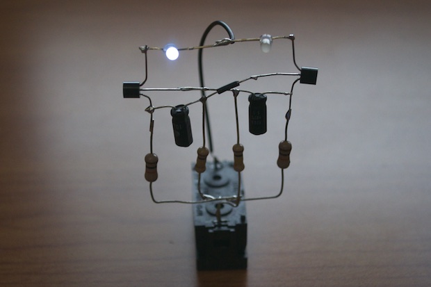
Here's another short video of the final assembly in action:
Pretty neat, right?


