DIY Breadboard Upgrades
Jan 19, 2013 Filed in:
Hacking | UpgradesBack when I built the
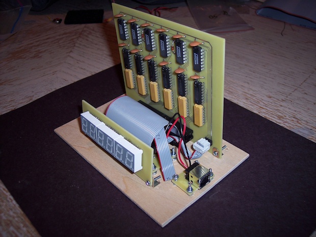
7490 clock, I needed a platform to attach everything to while I was ironing out the kinks. I wanted to get the layout and spacing just right before I started drilling holes in the final enclosure. The enclosure I had custom built took weeks to come in, so I didn’t want to screw it up and have to order another one.

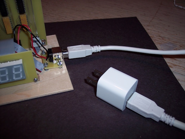
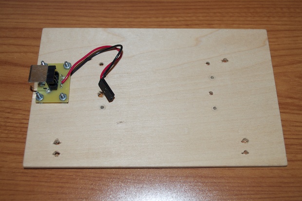
It was a lot sturdier and easier to work with rather than having to constantly wire it into my breadboard. To power it, I put together a little USB breakout board so that I could plug it in with an iPhone charger.

I never did finish that clock. The RTC chip that I used was pretty lousy. As a result, the clock intermittently runs really fast. It’s unusable as a clock. It’s not something I can overcome by manually adjusting the time once or twice month. It’s off hours a day.
So I was left with this little fixture with my custom USB breakout board. Since I now have some experience with the
DS1307 and
DS3231 RTC chips, I decided to
revisit this clock once more and see if I can finally make it functional.

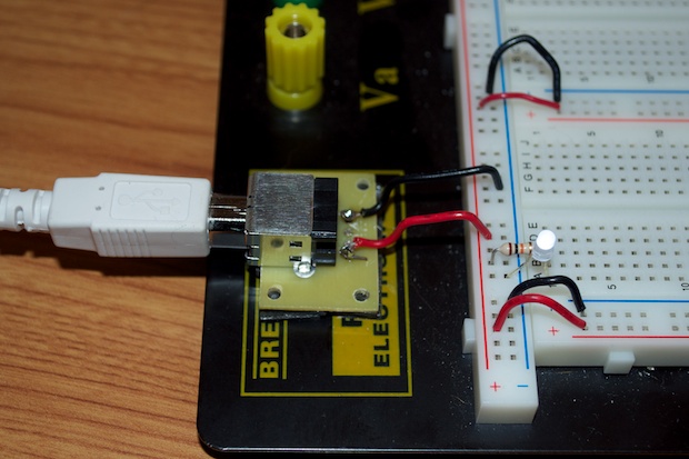
Instead of using the fixture, I decided to attach the breakout to my new breadboard. This will really come in handy. Now I can just plug the board in using any 5V USB adapter. That way I don’t have to power the board off my Arduino or my computer. If I ever short something out by accident, I’d rather trip the breaker than kill my computer.
I also added an LED so that I can tell the board is powered. This also helps when there’s a loose connection causing a short. The LED will flicker (or go out) if I’m shorting something out. I came up with that idea when I was working on prototyping the
Word Clock. Every now and then as I was working on the display, the LEDs would flicker and go crazy. It turned out that I had some wires pretty close together towards the shift registers and they were shorting out some of the pins. Luckily, I didn’t damage anything. So having some visual feedback is a good idea.


