Large 7-Segment Clock, Part II
May 18, 2015 Filed in:
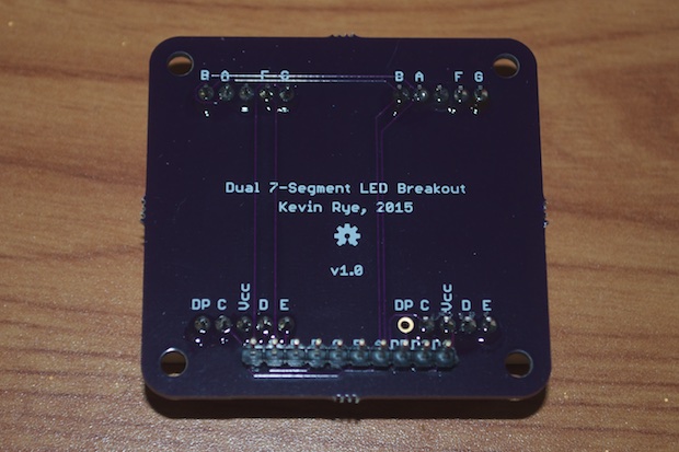
Electronics | Clocks | PCBsAfter a 13-day wait, I had my
7-segment LED breakout boards in-hand.
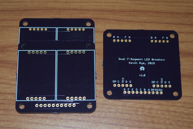
They came out perfect.
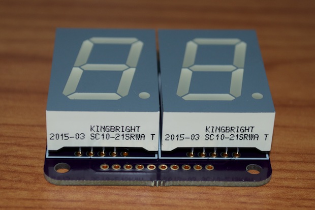
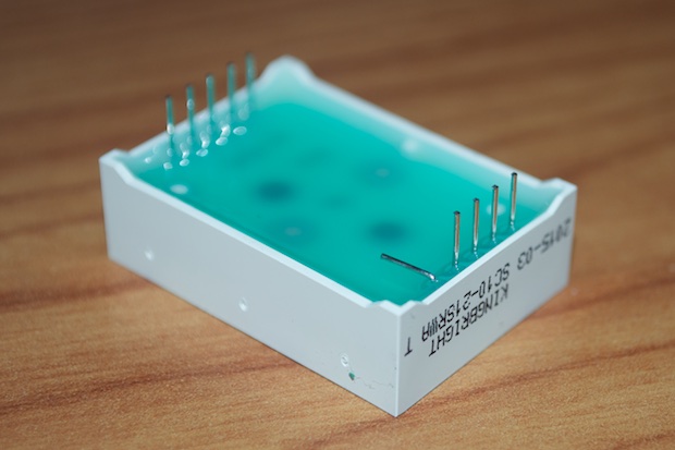
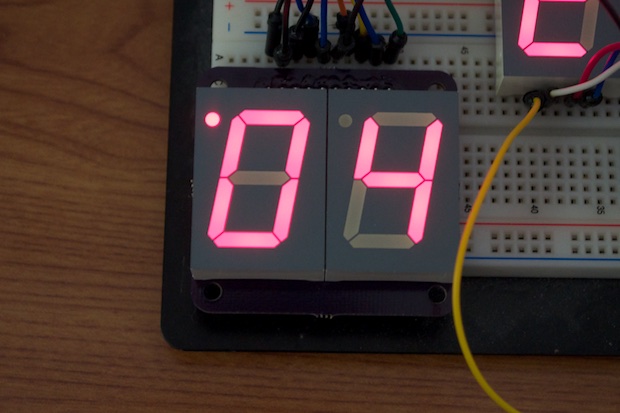
Since I'm not multiplexing the AM/PM LED in code, I need to make sure that only the first digit on the right has the decimal point soldered. I suppose I could cut the trace on the other digit, but it's easier (and cleaner) to just bend the one pin out of the way.
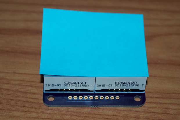
Always make sure you remember to cover your LEDs with something before you solder them. I like to use a small sticky pad. Flipping them over to solder the pins on the back is a good way to scuff them up. Trust me, I've done it.
It was a very easy build since all the resistors will be on the mainboard. It only took about a minute to solder one of the boards together.
I popped it back into my breadboard and reran the wires. It works great, and only the one decimal point is illuminated. Success!
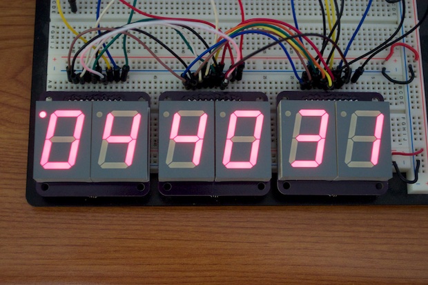
I then put the other two together. For the minutes and seconds sections, I went ahead and soldered in the decimal pins since they will not be physically routed on the main controller board.
The colon PCBs were trailing behind by a few days, so I had to wait for them to show up. I can't put the wraps on the 3D-printed frame without them. I was very happy to see them when they arrived.
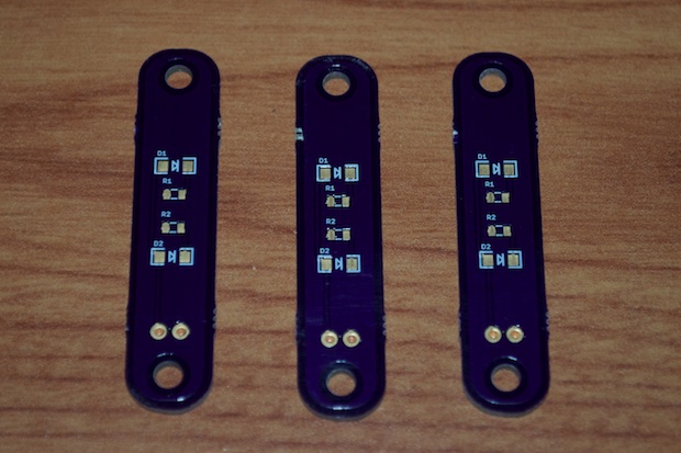
Assembly was a snap. It only took a few minutes to put two of them together. I'm using 470 ohm resistors across the board. It doesn't look like it in the picture, but I think the brightness is comparable.

I just have to wait a few more days for the controller board and I can wrap this one up. In the meantime, it's time to get to work on the 3D-printed frame…
See this project from start to finish:
Large 7-Segment Clock, Part I Large 7-Segment Clock, Part II
Large 7-Segment Clock, Part III Large 7-Segment Clock, Part IV
