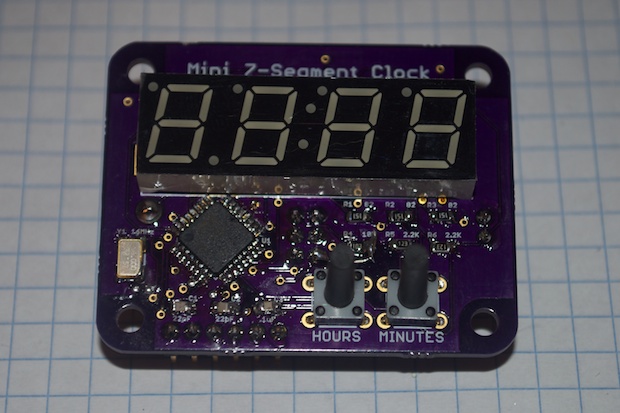
I received the PCBs for version 2 of my Mini 7-Segment Clock. They look awesome!
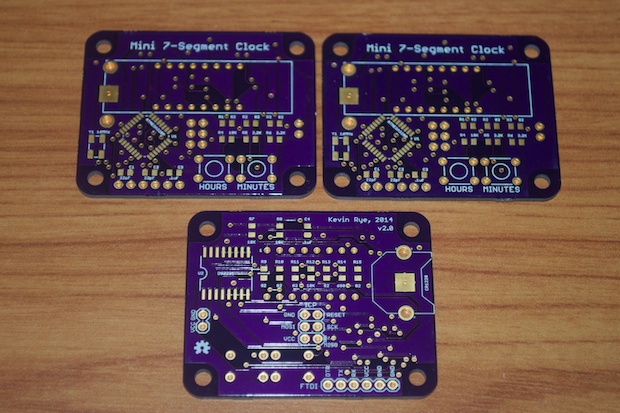
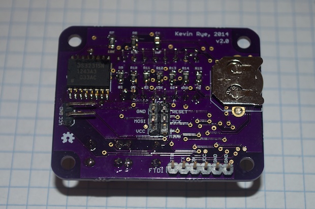
I managed to make it 10mm smaller than version 1 by swapping out the 28-pin ATmega328 for the SMD version. Although it’s that much smaller, I was still able to add an ICP and FTDI header.
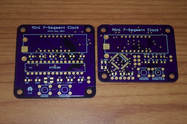
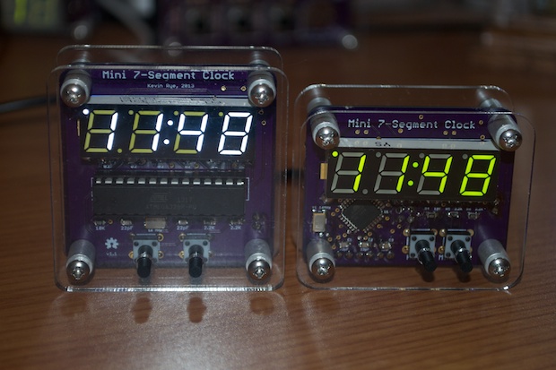
Here's a side-by-side comparison with version 1. It's so much smaller that I should have called it the Micro 7-Segment Clock!
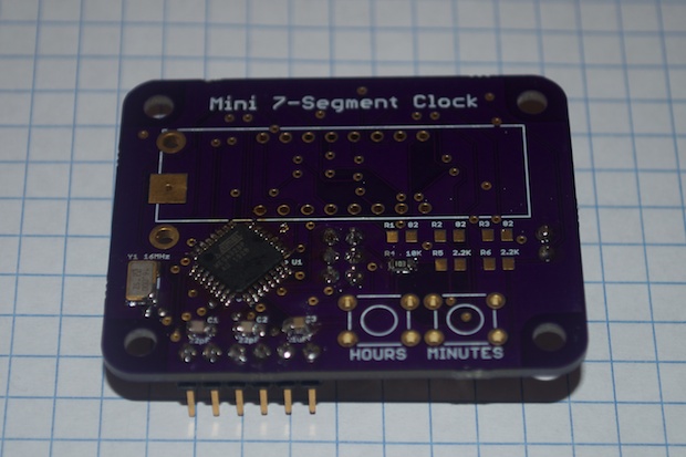
I didn’t want to put the whole thing together and find out that it didn’t work. That would have been a waste of components. I decided to only solder in the ATmega, the 16MHz crystal, and the supporting caps and resistors; just enough so that I could test loading the bootloader onto the ATmega and upload a sketch.
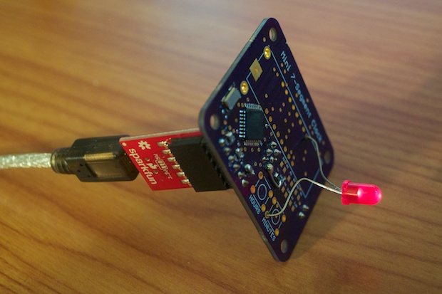
I configured my Arduino Uno as an ISP and attached the Mini Clock’s 6-pin ICP header to the Arduino via a ribbon cable and some jumpers.
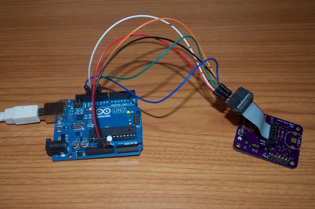
I then jumped into the Arduino IDE and burned the bootloader for an Uno. After the bootloader was successfully loaded, I connected my FTDI adapter and uploaded the blink sketch. I then jammed an LED into my PCB and watched the LED blink. Success!
After validating ICP and FTDI functions, it was safe to go ahead and solder in the rest of the components.
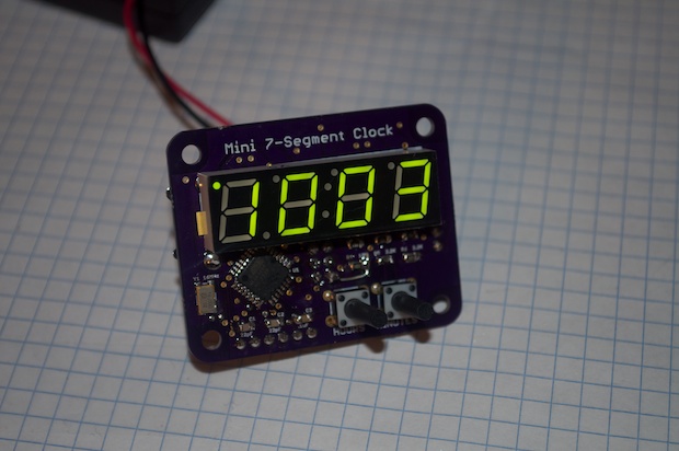
Now for the moment of truth. I crossed my fingers and connected a battery pack. Woo hoo! It works! I love that feeling you get when you spend weeks working on a project, it all comes together in the end and it just works.
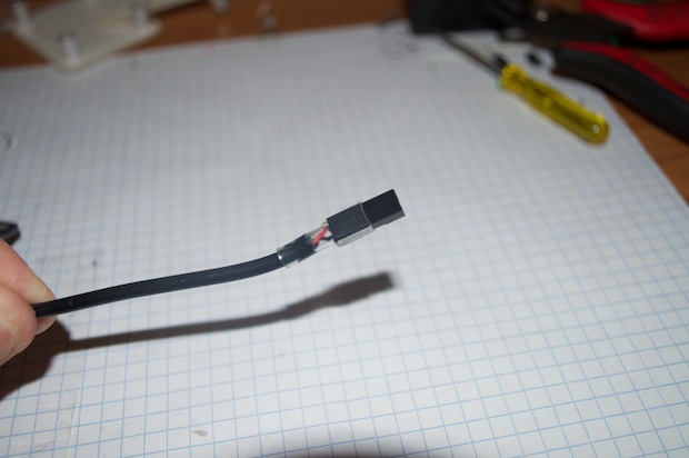
With the electronics working, it was time to put it in the enclosure. I cut the end off a SparkFun 5V DC power supply and soldered on a 2-pin Dupont connector. I then secured everything with a little heat shrink tubing.
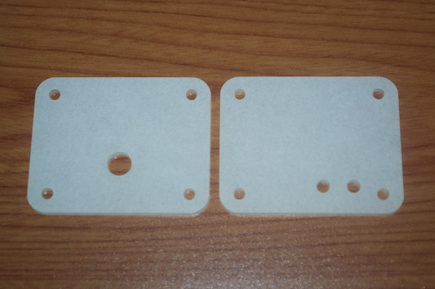
I then took the acrylic panels that I designed and had laser-cut from Ponoko and secured them to the clock via some screws and standoffs.
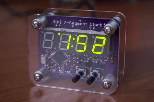
It looks amazing! I’m really happy with the way that it came out. I also really like the “kelly” green segments on this display.
Here’s another side-by-side comparison with version 1. I remember being so pleased with version 1 after I made it. At the time, I didn’t think I could make it any smaller, and yet I did!
I wonder how much smaller version 3 will be? Nah! I think I’ll quit while I’m ahead! Besides, I don't think I could make it any smaller without using a smaller display.
See this project from start to finish: Mini 7-Segment Clock V2, Part I Mini 7-Segment Clock V2, Part II

