It’s only been 3 weeks since I got my hands on some
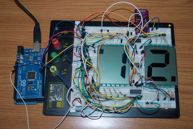
3” LUMEX LCDs, but already I have made some fantastic progress with this clock.
With the
LCD Display Boards designed and ordered, it was time to put together the PCB for the main clock controller. I decided to stick with my original idea of having two ATmegas onboard. One for the main clock, and another dedicated to outputting the 60Hz phase signal for the LCD backplanes. I just like the idea of having a single chip dedicated to that function. However, it seems like a total waste to have an ATmega328 onboard and only make use of one digital pin. For this. I decided to go with an ATtiny85. I just happen to have a few on hand, so I uploaded my sketch to an ATtiny85 using my
ATtiny Programming Shield and popped it into my breadboard.
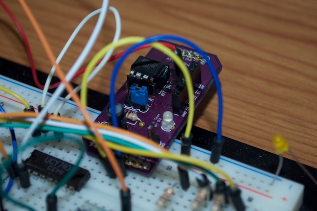
It works like a charm.
I’d love to go all-SMD, but then I’d need to put in some extra stuff in order to bootload the chip and upload my sketch. The space I’d save going with an SMD package, I’d lose adding the ICSP header. For that, I decided to just stick with the 8-pin DIP package.
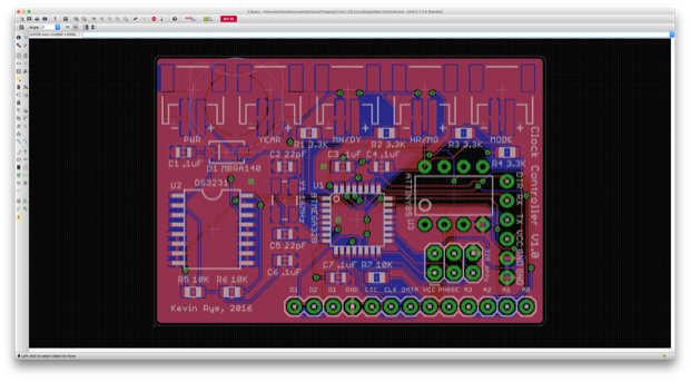
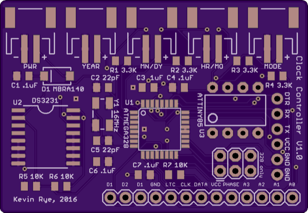
I had a few pins left over, so I broke them out to the header with everything else. This is such a generic clock board that maybe some day I’ll use the other two boards that I’ll get from OSH Park in another clock. That extra I/O might just come in handy.
With all the boards now ordered, it was time to start working on the 3D model. This will help me envision what kind of enclosure I’m going to build for it. I want to keep it super-thin.


I have a few button boards left over from my
Nixie Clock, so I think I’ll use one of those for the buttons. Instead of having them on the back, I’ll put them on the side.
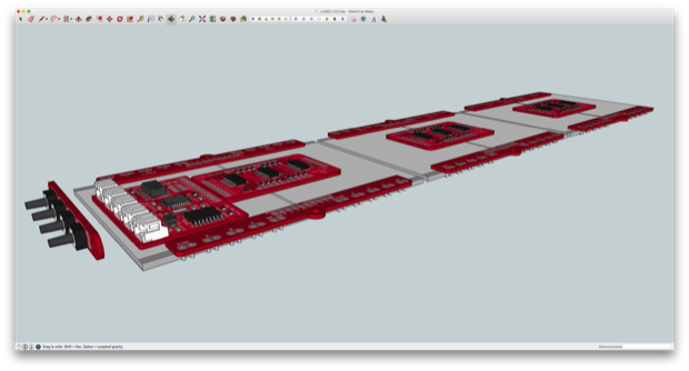
I printed the model out to better visualize how everything will be wired together. I might be able to move things around a bit and connect the displays to the driver boards with 10-pin headers and sockets. I won’t know for sure until I have them in my hands.
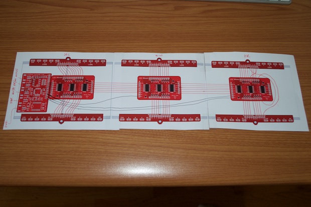
Now I just have to wait a few weeks for the PCBs to arrive.
See this project from start to finish: LUMEX 3" 7-Segment Displays 3" LCD Clock - Part I 3" LCD Clock - Part II
3" LCD Clock - Part III 3" LCD Clock - Part IV 3" LCD Clock - Part V 3" LCD Clock - Part VI


