I really liked the way that my
Bare Bones Arduino boards came out.
Both versions. They’ve really come in handy. They’re great for throwing quick projects together.
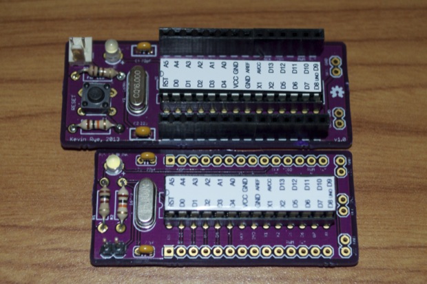
I never put holes on them so that they could be mounted. The main reason behind not placing mounting holes on the PCBs was two-fold. First, I wanted to make the boards as small as possible to keeps cost down. Secondly, I never intended on mounting these boards. They were more so for things that would just get tossed in a project box and maybe secured with a drop or two of hot glue; if they even needed to be secured at all. (Something like what I did with the RGB Night Light and the Tesseract.)
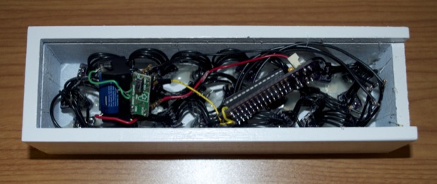
For the
RGB Night Light, the PCB didn’t even need to be mounted. I just shoved it in the enclosure along with all the other guts.
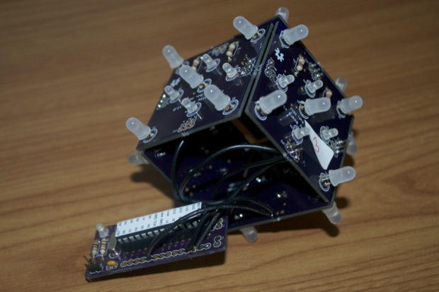
For the
Tesseract, the PCB was secured to the bottom of the LED boards with few drops of hot glue.
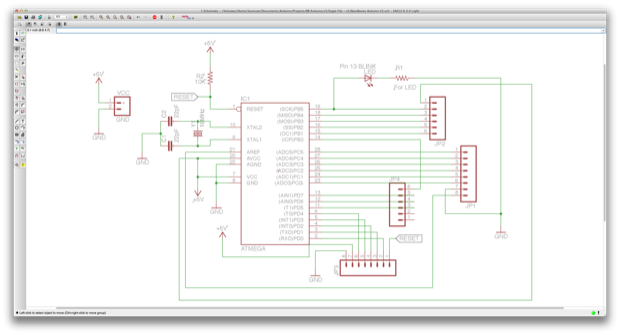
However, I’d like to make a new version of the Bare Bones Arduino PCB with holes so that they can be mounted between some sheets of acrylic. I’d also like to swap out all the through-hole components for SMD versions.
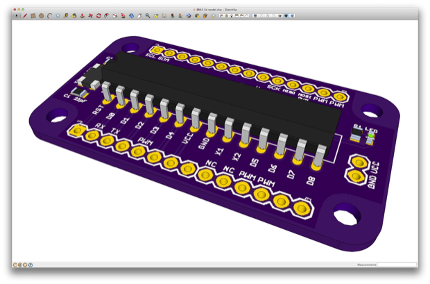
I took the Bare Bones V2 schematic, and got to work.
I then created a new outline for the PCB that included mounting holes. I basically just resized one of
Dangerous Prototypes Sick of Beige footprints. I also want to be able to stack some shields on top. I could have made it a little thinner, but I left a little bit of space so that the shields will have a little more real estate between the headers.
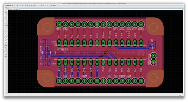
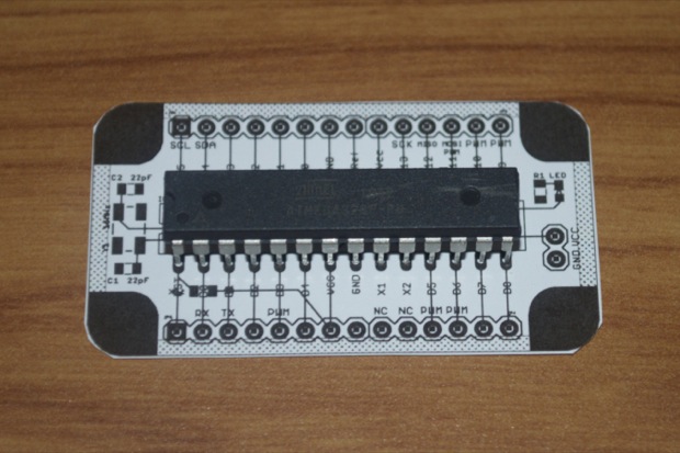
I then printed it out just for kicks. Even though it’s a tiny bit larger than the BBA1 and BBA2, it’s still pretty small.
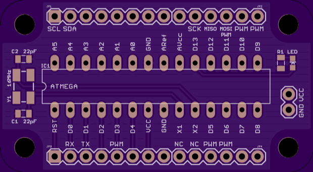
Here’s the OSH Park render:
I even chalked up a 3D model in order to get a better feel for how it will look with shields attached. (When I design one, that is.)
After I had submitted my design, I got to work on the enclosure. Using the dimensions from Eagle, I chalked up a design in SketchUp.
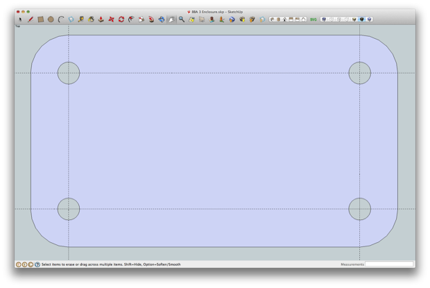
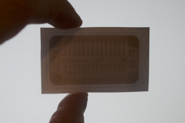
Again, I printed it out just to see what it looked like. I taped the BBA3 PCB printout to the back of it and held it up to my monitor just to make sure that my spacing was good. I left a 1/6th” overhang on all sides.
With that looking good, it was then just a matter of exporting the SketchUp file as an SVG file. I then took it into Inkscape and filled the template for
Ponoko. I fit 15 on a 7” x 7” sheet. That’s enough for 7 assemblies, with one left over as a spare.
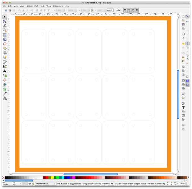
The PCBs cost $11.10 for 3 and the acrylic cost $7.30 in materials and cutting. I paid an extra $5.48 to rush it. In the past it’s taken up to 2 weeks to turn them around. With the extra fee, they promise to have it done in a day.
With the rest of the components, a complete assembly should only cost me about $5 bucks. Not too shabby.
Hopefully I get the PCBs and the acrylic around the same time. I hate when a project gets held up waiting for parts.
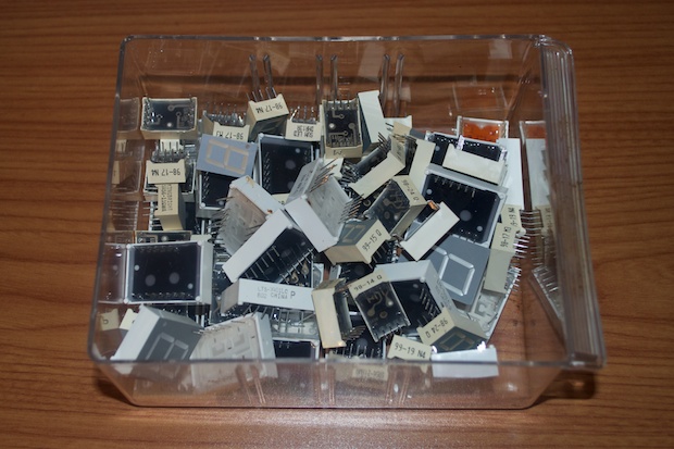
I already have an idea for a shield. I have a ton of 7-segment displays that I’ve sourced over the years. It’s time to use some of them up.
 See this project from start to finish:
 Bare Bones Arduino V3, Part I
Bare Bones Arduino V3, Part II
