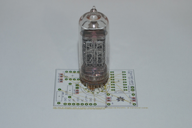
While waiting for the paint to dry on my IN-14
Nixie Clock, I decided to tinker around with a small board idea to do something with this lonely IN-19B that I have. When I bought the IN-14s for my clock, the eBay seller threw one in as a way to make up for a delay in shipping. It's a cool little tube. But what would I ever use it for?
I just want to throw together a little board that I can plug this tube into and watch it cycle through all the symbols. Nothing fancy.
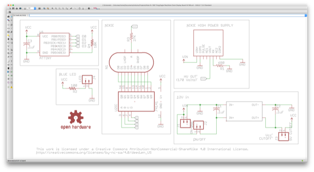
I threw together a schematic using piece-parts from my nixie clock.
I then laid the parts out to make the board as small as possible.
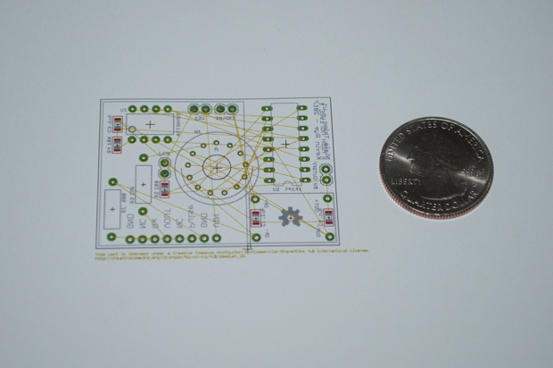
That's pretty small!
The high voltage power supply and the 5V regulator will go on the back. The PCB will be no bigger than it has to be.
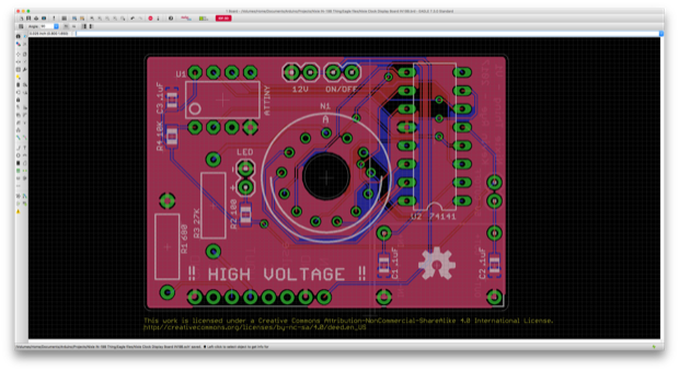
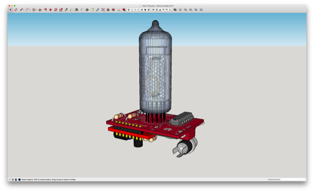
Being happy with the layout, I then routed the traces.
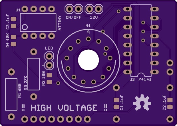
Here's the OSH Park render. Only $13.80 for three.

This is just a little thing to kill some time, and use up a useless tube. I did think about designing it so that it could also be used as a single-tube clock, but adding an ATmega328, a DS3231, and a backup battery seems like overkill for what it is. If I was ever to design a single-tube clock, I'd probably wait until I had a really big tube like a Z566 or a Z568. Then maybe it would be worth adding all the extra hardware.
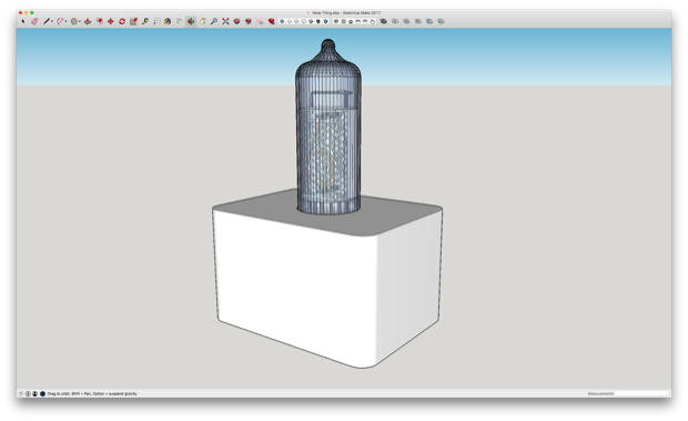
While I wait for the boards to arrive, I can play around with an idea for a case. For that, I put together a 3D model.
Making a case for it should be pretty easy.
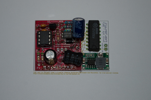
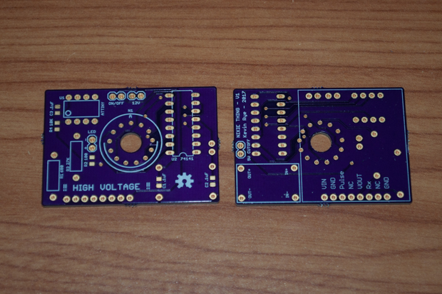
About two weeks later, my PCBs arrived.
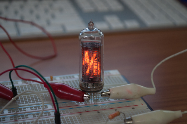
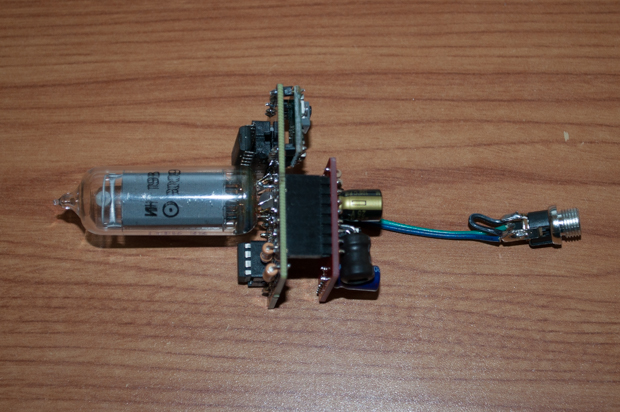
I then soldered in all my components. Soldering in that IN-19 with such short leads was very difficult. Some of the leads wouldn't even reach the holes. I had to the bridge the gab between the pins and the board with a solder blob.
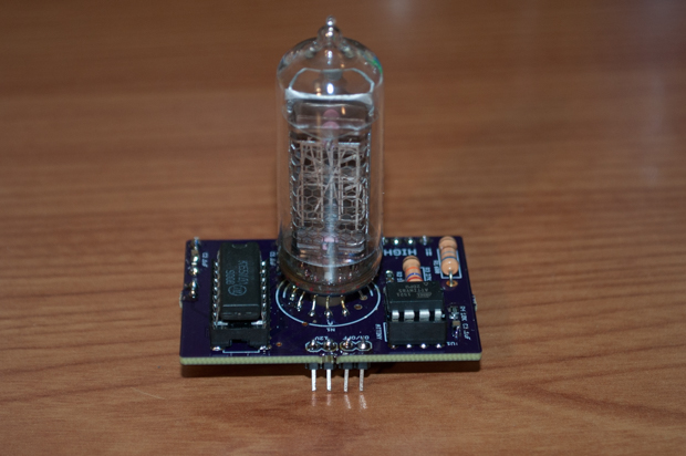
I soldered in a blue LED on the bottom and bent it up so that it would illuminate the nixie. Just in case this turns out to be a disaster, I soldered in a female header so that I could socket the power supply. If I even need it in the future for another project, I won't have to unsolder it.
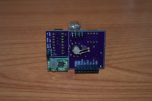
I then connected the DC input jack.
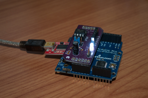
I flashed my ATtiny85 with some code. It's a pretty simple sketch. All it does is feed the 74141 nixie driver chip with BCD, using the 4 digital pins available on the ATtiny85.
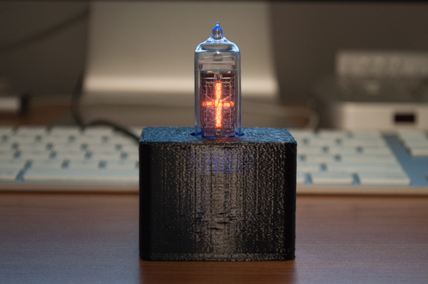
And there is it. It's a silly little thing, but what else am I going to do with an IN-19?
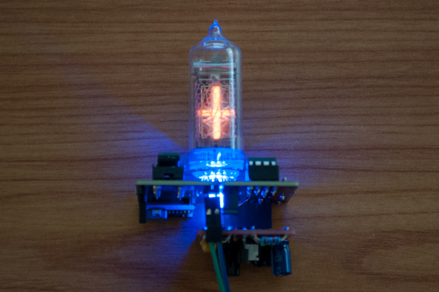
It's just too bad that it's only displaying six out of the eight characters. The whole point of this project was to make a little widget that cycles through the characters, and it doesn't really do a good job of that.
I was just messing around when I threw this board together. I made the rookie mistake of assuming that the IN-19 was the same as the IN-14 when it came to the pinouts. I don't know why I never bothered to double check them. As it turns out, the anode on the IN-19 is on the opposite side as the IN-14. As a result, I had to solder in the nixie backwards. Since the pinouts don't match up, it resulted in two characters that I can't light up.
Here it is in action…
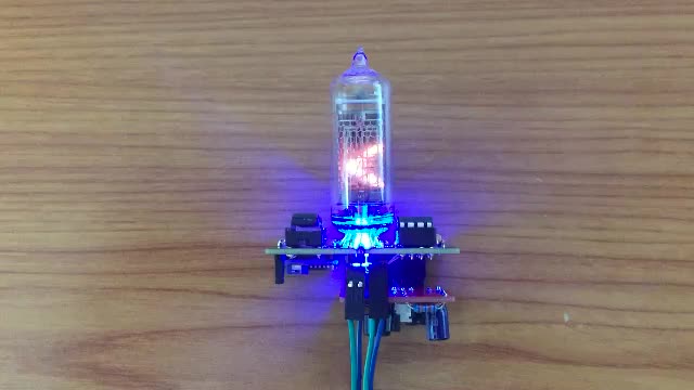
Anyway, not bad overall. Like I said, it's just a silly little thing. At least it "works". If anything, it was a good practice run for a single-digit nixie clock.
Might as well wrap things up with a little 3D-printing...