Other than a few code tweaks, the electronics are complete. It's time to work on the case. In order to nail down all the dimensions, I needed to create 3D models of the electronics.
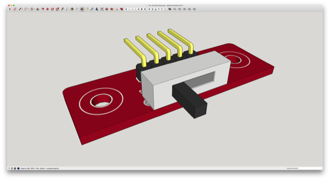
I created a model of the 4-way switch for the RGB LEDs.
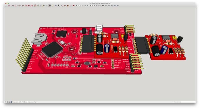
As well as a 3D model for the controller board and two high voltage nixie power supplies.
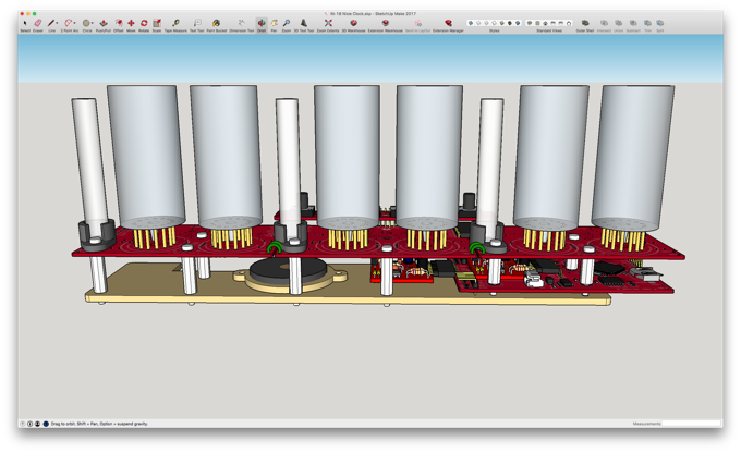
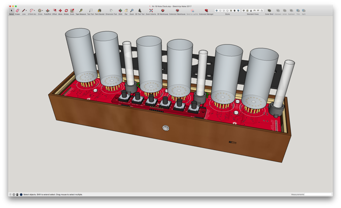
I then assembled the whole thing together in SketchUp and mounted it onto a board using some board stands.
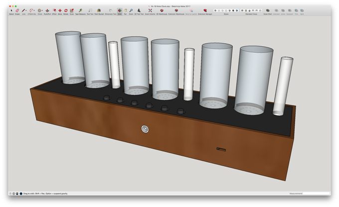
I then created a box to house the electronics.
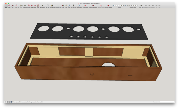
Everything should fit nicely.
I'm a little nervous about the hole placement on the top for the nixies and the buttons. I might do a few test cuts with some poster board before I commit to cutting the final piece out of acrylic. The top isn't going to be screwed in. It's friction fit, so it needs to be perfect.
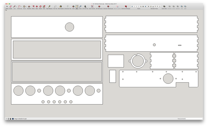
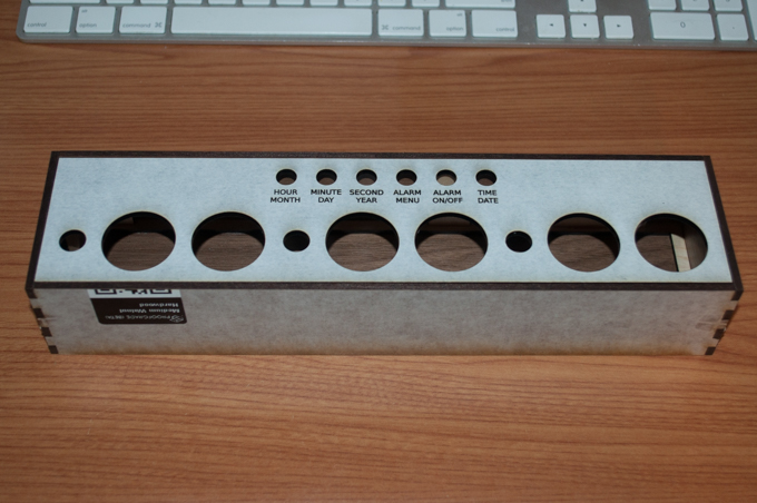
I exported all the faces as SVGs and took the back and top panels into Inkscape to add some text.
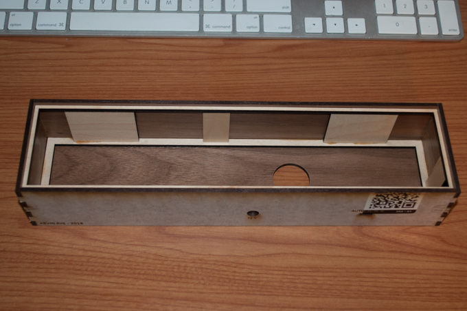
I first mounted all the electronics on the base plate. Everything fits perfectly. I hot glued the speaker into place and used epoxy on the standoffs.
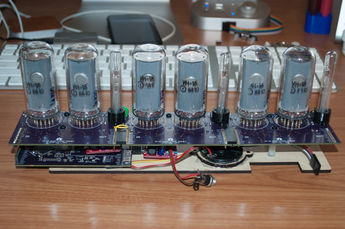
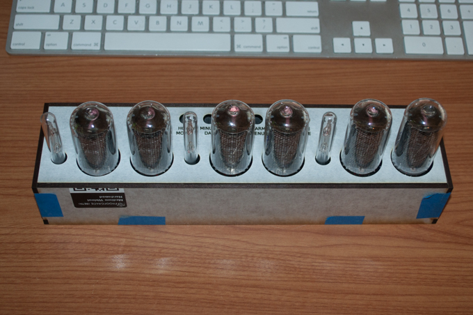
I then cut out all the other pieces and held it all together with some blue tape to test-fit the electronics.
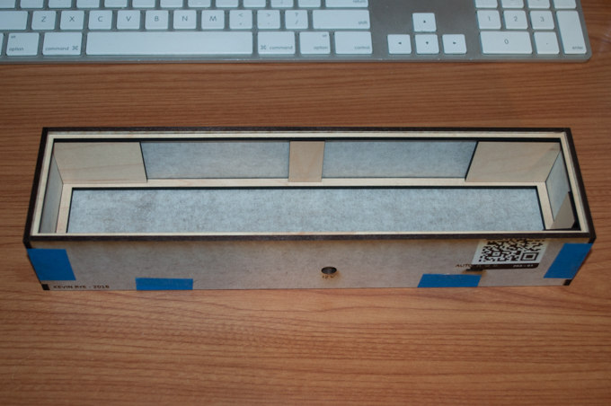
They fit perfectly.
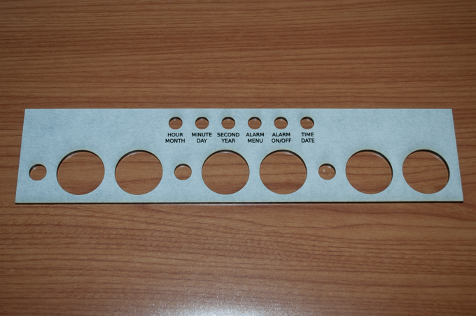
I did a few test cuts out of poster board to nail down the hole placement. As I suspected, it took a few tries before it was perfect.
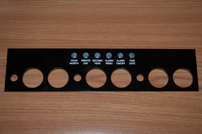
I then cut the final one out of black acrylic and engraved the text.
It's a perfect fit. It snaps right in.
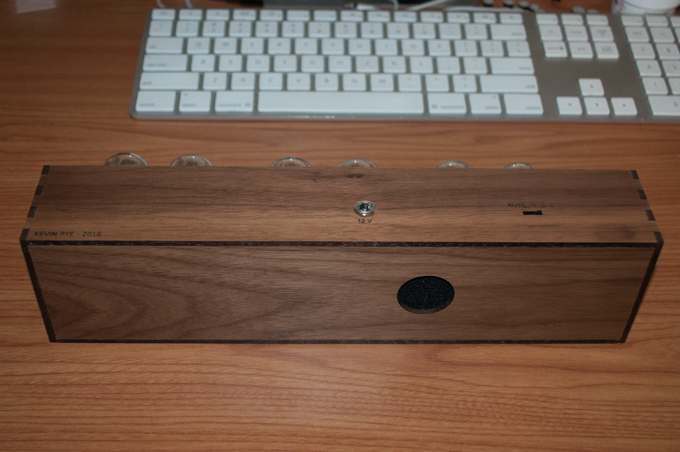
I then glued everything together, clamped it, and let it sit overnight.
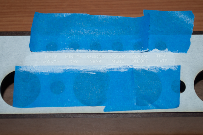
The last thing to do was mask off the letters and fill them with white acrylic paint. I used black on the letters on the back.
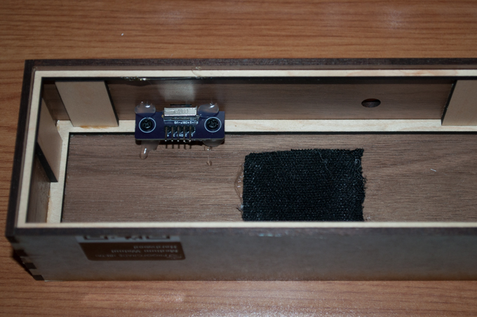
I glued the 4-way switch breakout into position and glued a piece of speaker fabric over the speaker hole.
I glued the button board to the underside of the acrylic top.
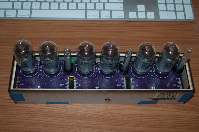
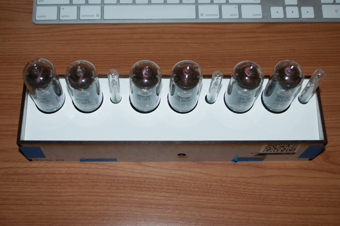
Lastly, I installed the electronics, and snapped the top on.
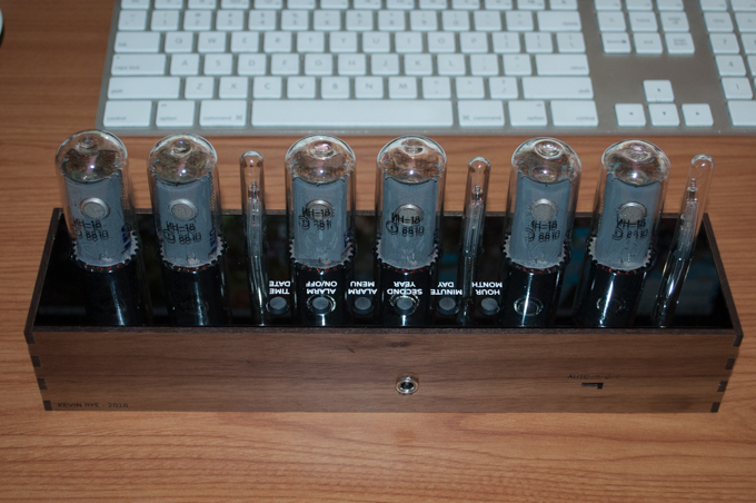
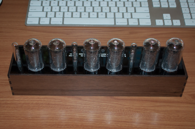
All done. It looks awesome.
I might put some rubber feet or something on the bottom just to make a little air gap for the speaker. I haven't decided yet.
The moment of truth. I plugged it in and crossed my fingers that I didn't knock any cables loose during assembly. It was a little tricky getting everything in. It was like building a ship in a bottle.
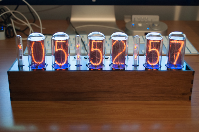
I can't believe it took four months to complete. It came out awesome. It was well worth it to be patient and do everything right.
See this project from start to finish:
IN-18 Nixies TPIC6B595 Shift Registers IN-18 Nixie Clock - Part I NE-2 Neon Bulbs IN-18 Nixie Clock - Part II IN-18 Nixie Clock - Part III IN-18 Nixie Clock - Part IV IN-18 Nixie Clock - Part V

