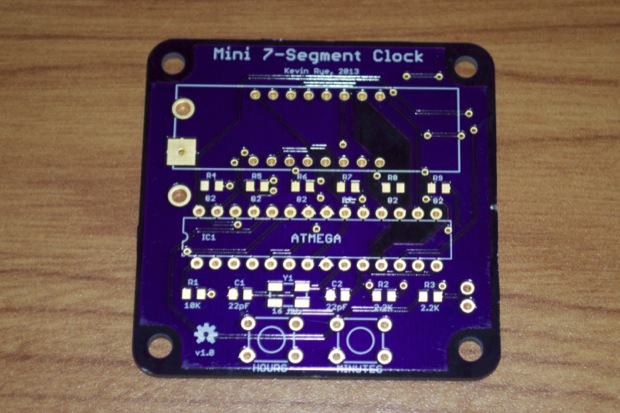
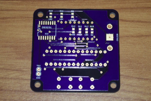
I received my Mini 7-Segment Clock PCBs. I’m pretty excited to put one together. I think it’s going to look pretty cool, being so tiny.
I’ve always liked 7-segment displays. With the popularity of LCDs, TFTs, and touch screens, etc, you’d think these displays would be obsolete by now. If you keep an eye out for them, you’ll be amazed at just how many times they pop up. Everything from microwaves to dishwashers. We have test equipment at work that costs thousands of dollars that use these cheap $2 displays. Even though they are still pretty popular today, I’ve always thought of them as rather “retro”.
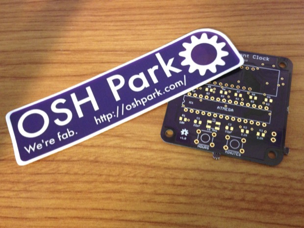
OSH Park started throwing in some schwag. A very nice touch.
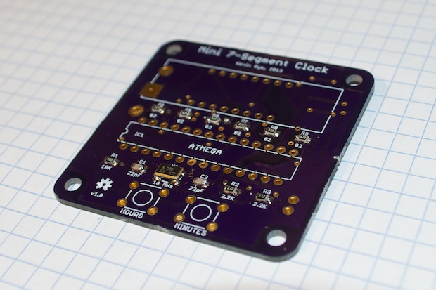
I got the boards ready to go by taking my Dremel to the break-away tabs around the edges. I then stared by soldering in the crystal, the caps, and the resistors.
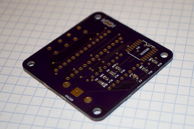
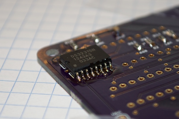
I then soldered on the DS3231. Tricky with those 16 fine-pitched pins, but it came out pretty nice.
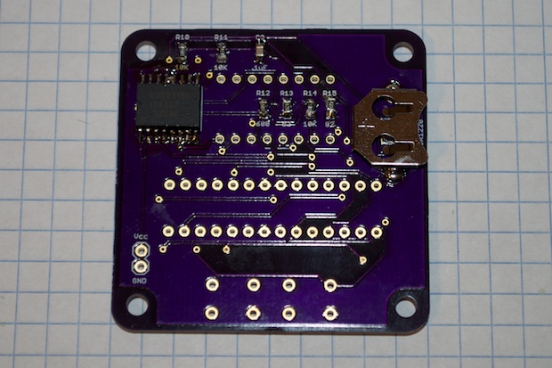
I then soldered in the coin cell holder for the DS3231’s battery backup.
I then soldered in the 28-pin DIP and the 2 push buttons.
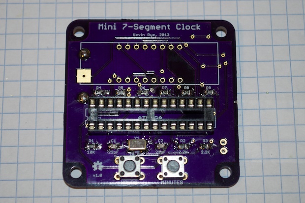
To keep the width of the clock as small as possible, I attached a right-angle 2-pin header for power.
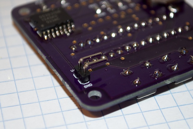
A 2-pin Dupont connector will eventually be soldered directly to the 5V DC adapter. I’ll just cut the leads off and solder one on. No need for a huge, bulky connector. With it sitting flush with the PCB, I can keep the overall thickness of the clock to a minimum.
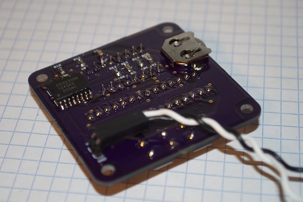
Finally, I soldered in the 7-segment display.
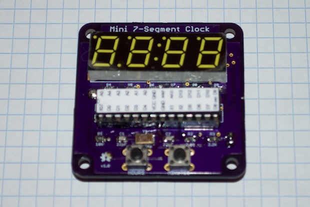
Despite my best efforts, that dog won’t hunt!
I got out my logic probe and started prodding around. Everything that should have Vcc and ground checks out, but the ATmega is not running. All the resistors measure what they should. The buttons go high and low. There are no shorts. No solder bridges. No dry joints. What gives?
I though maybe I nuked the crystal, so I replaced it. No dice. The ATmega still does not run.
Did I cook the caps? Replaced those. Still no dice.
No matter what I do, the ATmega just doesn’t run. I pulled the chip out and put it back in my Arduino board. I then jumpered all the pins to the DIP socket on my PCB and fired it up. It works!
So what’s the deal? By doing this, I’m bypassing the crystal and the caps on my PCB. So it must be that.
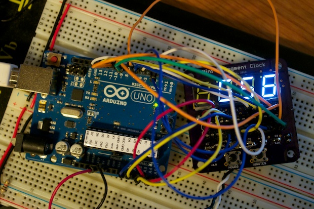
I touched up the board where the caps and the crystal are, but still nothing. I must have broken a trace or lifted a pad or something. I double checked the schematic just to be sure and there’s no reason why it shouldn’t work. The only thing I could think of is that the part in the SparkFun library doesn’t show pins 1 and 4 as being grounded. Just for fun I grounded those 2 pins, but it didn’t make a difference. Then I thought about it, I used the same footprint on the
SpeakJet board and that worked fine. So grounding those 2 pins is probably optional.
I bit the bullet and put together another one. Boom. Must have been a bad trace all along.
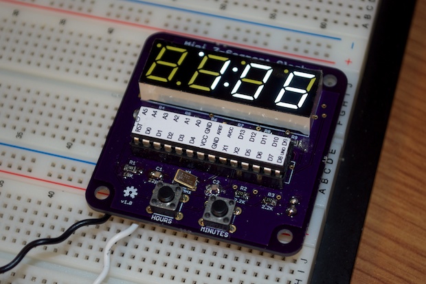
During the troubleshooting, I had discovered an error on the board. I wondered why my colon wasn’t blinking, despite the fact that the DS3231 is ticking along happily at 1Hz. I checked the signal on pins 10 and 12 and they're pin-swapped. Not my fault! I looked at the schematic and compared it to the datasheet. Everything looked OK. I knew I triple checked all my pinouts. So what gives?
Pins 9 and 10 are not hooked up on the schematic, but on the PCB it’s pins 9 and 12 that are not connected. Huh?
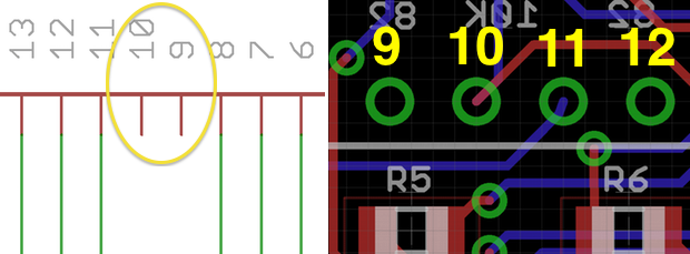
I ran the error checker and it came up empty. I then inspected the footprint for the part. Ah ha! Whatever dingbat that designed the footprint for the part got the pins backwards. Who would have known?
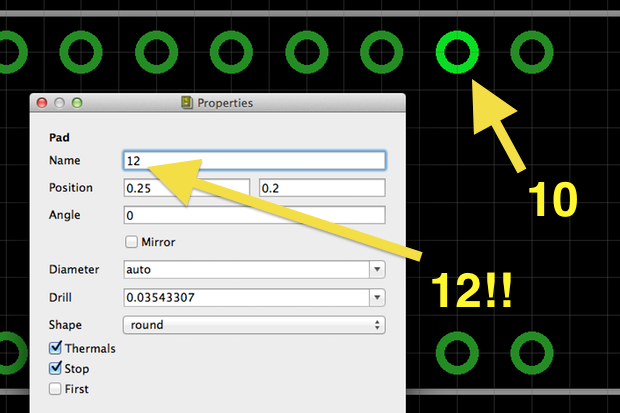
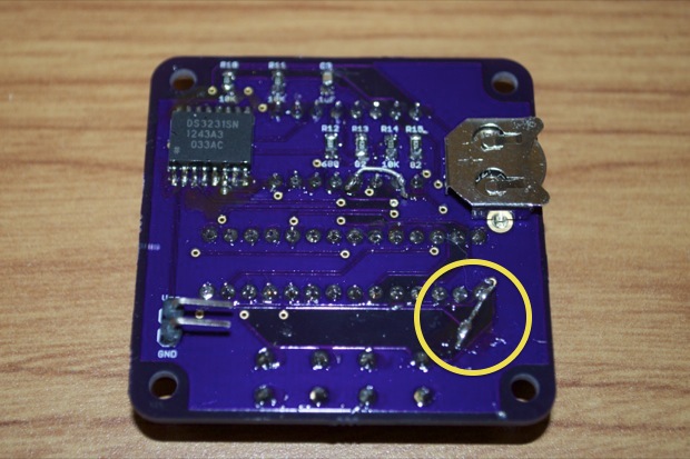
It’s an easy fix, but an ugly one. I just jumpered pins 10 and 12 with a little wire. (Good thing I’m not using the dot LED!)
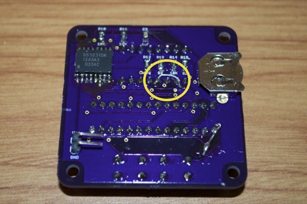
Another problem that I found was that the way I had Vcc running to the chip was a little convoluted. I fixed that by adding a little jumper to the back.
For the power supply, I took a SparkFun 5V adapter and cut the plug off.
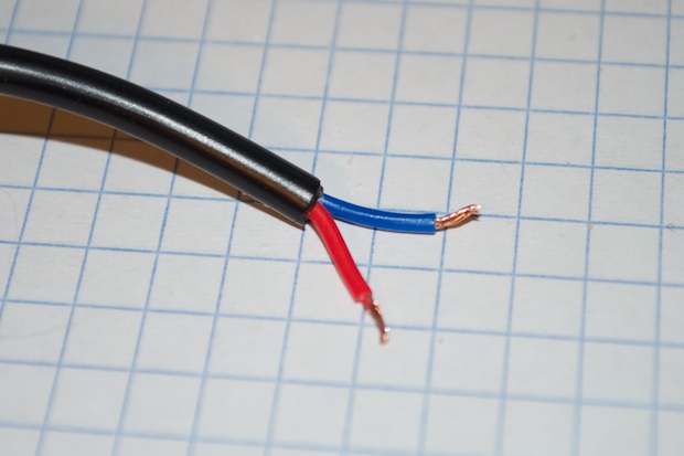
I then soldered on some crimp pins.
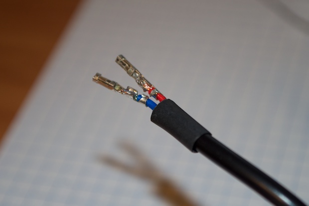
I slide on the 2-pin Dupont connector...
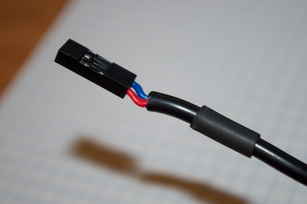
…and used my hot air rework station to melt the shrink tubing.

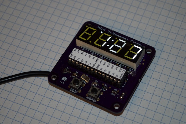
I plugged it in and it worked like a charm.
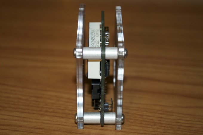
As far as an enclosure goes, some laser cut 3mm acrylic will do fine. I used some of the leftovers from my SpeakJet project to use as a reference. I can put it together and keep it as thin as possible with some 3/8” and 1/4” standoffs and some 5/8” and 1/4” screws.
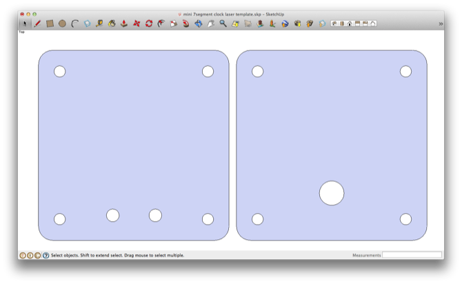
The final case design will just have 2 hoes in the front for the buttons and one in the back for the power cord.
It’s going to be pretty hard to press the buttons once the acrylic is in the way, so I think I’ll swap out the buttons with some 10mm tall ones. You can get 100 from China eBay for $5 bucks.
I’m going to fix the 2 mistakes that I found and get some new boards made. I guess I have time; it takes a good 20 days for Ponoko to turn around an order.
See this project from start to finish: Adafruit SMD Book Mini 7-Segment Clock Mini 7-Segment Clock, Part II Mini 7-Segment Clock, Part III
Mini 7-Segment Clock, Part IV


