Rev 2 of my
LCD clock is a little slow going. I took a step to the side to wrap up rev 1.1 of my
7 segment clock. I’ve submitted my Eagle file to OSH Park as well as the laser file for the acrylic to Ponoko. All my parts are on-hand. I’m just waiting for the PCBs and the acrylic and I’ll be able to put the wraps on that one.
In the meantime, my mini audio amp practice boards came in. I wasn’t too sure if I’d be able to solder the TPA2005D1 chip or not. Rather than waste $45 on the LCD Clock V2 PCB and make a mess of it, I figured it would be a good idea to make a practice board based off SparkFun’s breakout board. If I can’t solder the part by hand, then I’ll just incorporate SparkFun’s audio amp breakout into my clock PCB as a daughterboard; similar to what I did with the
SpeakJet board.
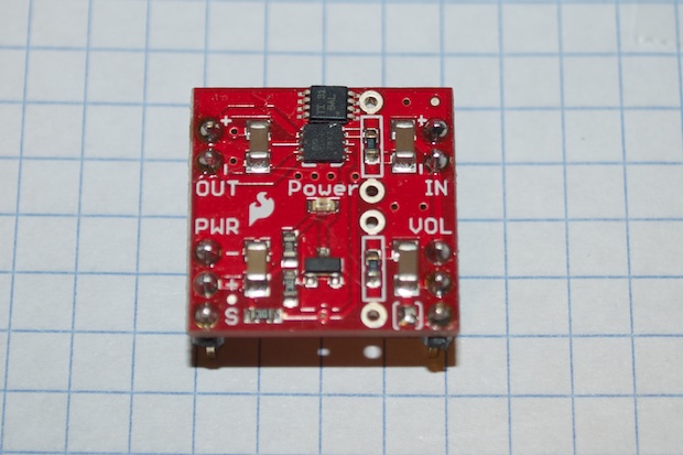
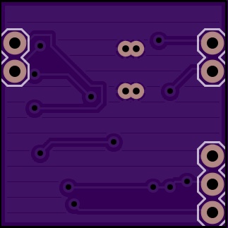
Here’s the mini audio amp PCB I had made.
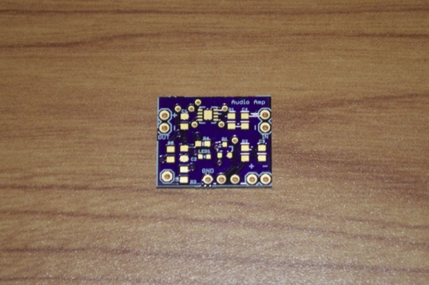
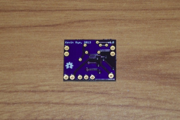
It’s a tad bit smaller than SparkFun’s since I removed the volume pot and the pads for the optional resistors. Originally I was just going to put a bunch of TPA2005D1s parts on a PCB and call it a day, but I figured if I pull it off, might as well make the boards functional. They may come in handy in the future.
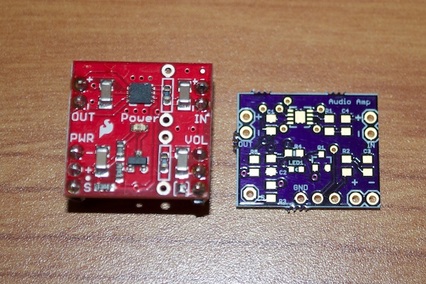
Man is this thing tiny!
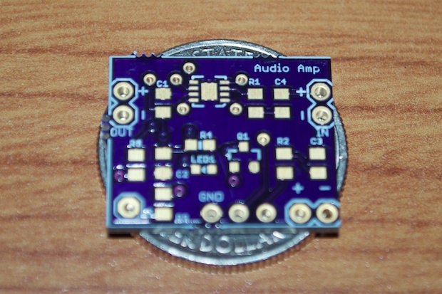
As it turns out, I ordered the wrong part from DigiKey.
Curse you impossible to navigate DigiKey part finder! I ordered the 8MSOP package instead of the 8SON one. As tiny as it is, it’s still bigger than the 8SON package.
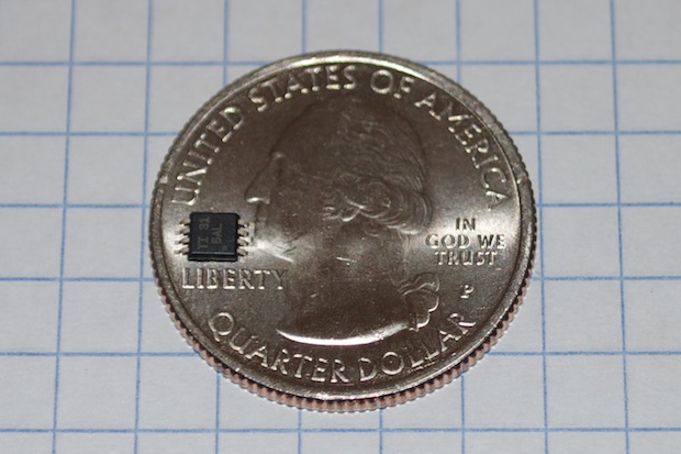
This might be a good thing! After seeing them side-by-side, it’s pretty clear that the 8MSOP is the way to go. I’m convinced. There’s no way I’m going to be able to solder an 8SON package.
What does this mean? This means I need to respin the board. It should be as easy as right-clicking on the chip and changing the package for the part. Unfortunately, Eagle gives me an error about pins not being connected when I try it. I can’t even edit the part because it’s not in SparkFun’s library.
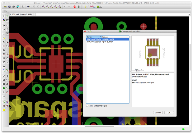
I had to create my own.
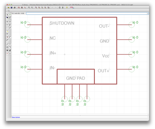
I could have just used a regular 8MSOP package, but the TPA2005D1 needs to have an additional ground pad under the chip for heat transfer. Adding a few vias also helps to dissipate the heat by turning both ground plains into heatsinks. The TPA2005D1 is pretty efficient and doesn’t get too hot, but the spec sheet is pretty specific about adding it. SparkFun added it to their board, so I’m adding it too.
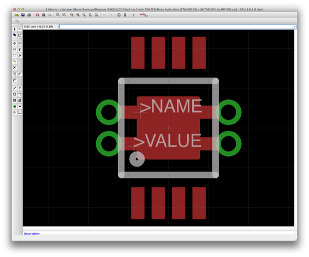
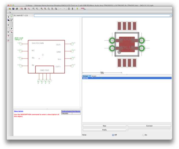
Once the package and the symbol were complete, I combined them to create a new device.
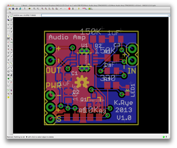
I then dropped it into the SparkFun breakout board and moved things around to make space. Normally I slave over the details and make things perfect, but this is just for solder practice, so I banged it out in about an hour. (Including the TPA2005D1 design.)
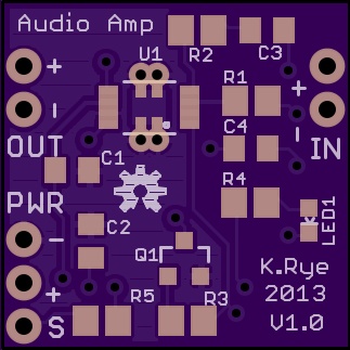
It’ll only cost $3.25 to have 3 made. I kept “V1.0” on there. I guess I should have changed it to “V2.0” but I guess I could just pretend the other board never happened.
 See this project from start to finish:
LCD Clock Version 2 - Design Decisions Mini Audio Amp, Take 1… and 2
Mini Audio Amp - Version 2 Build LCD Clock Version 2 - Part I LCD Clock Version 2 - Part II


