My new GPS button boards arrived in the mail. I can't wait to hack these into the clock. If I can finally get this clock working and into a case, I might finally be motivated to finish the code.
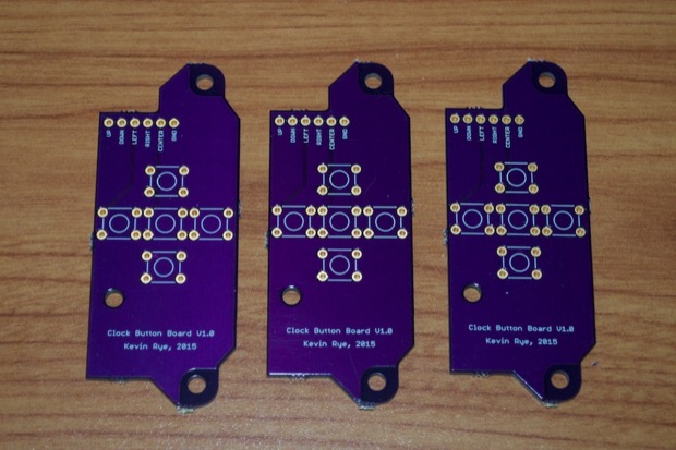
The hard part is going to be wiring it up. I have to unsolder the tiny 5-way switch and solder these buttons directly to the pads on the PCB. It's going to take some really thin wire, and a steady hand.
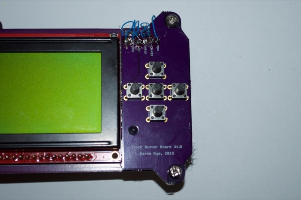
Since the 5-way switch has 8 solder points, I had to use my hot air rework station to remove it. Things got a little toasty and I browned the board a little bit, but nothing was damaged. I then took some 30 gage rework wire and soldered them directly to the pads of the 5-way switch. I used some hot glue to secure the wires in place.

It looks like hell, but it works. I then secured the two boards together with some spacers and more hot glue.
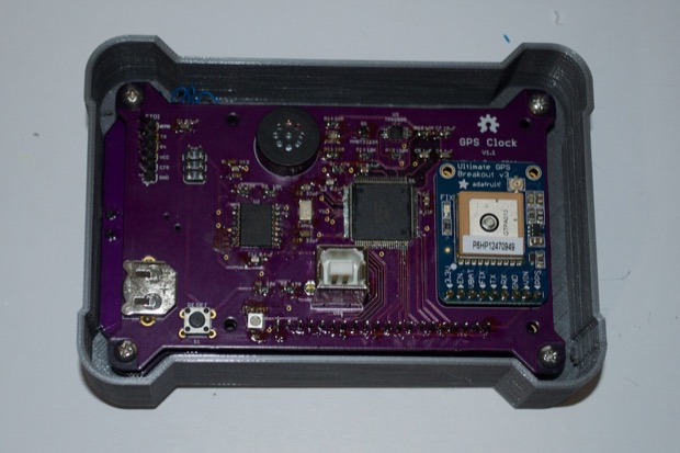
Finally, I screwed the whole assembly into my 3D-printed enclosure.
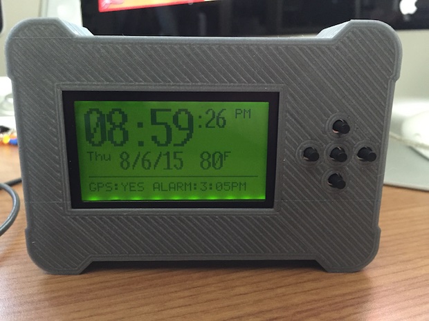
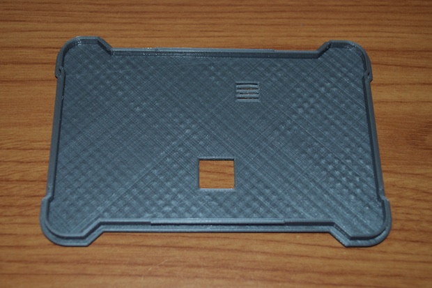
The case is looking pretty good, but the button holes need to be tightened up just a hair. Also, the LCD isn't perfectly centered within the cutout. So I think one last tweak and one final print is required. Not to mention, I printed this case with a layer resolution of .2mm. The diagonal lines are pretty evident. I think I'll print it at .1mm to improve the quality.
I also need to print the back of the case too. I got to work on redesigning the back to incorporate some little notches that'll allow the two pieces to snap together.
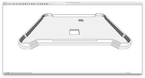
After a few hours, I had a pretty good looking print.
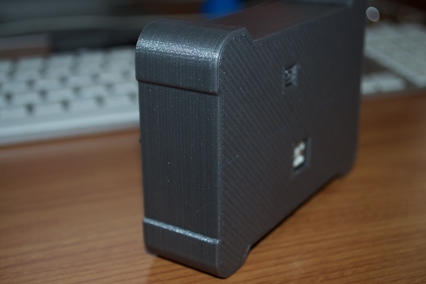
It's a pretty tight fit, but the two parts snap together perfectly.
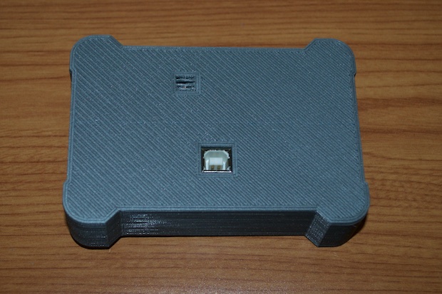
It's almost seamless. There's no way the back is coming off without applying some serious effort.
All that's left is to firm up the code and this one's a wrap.
See this project from start to finish: GPS Clock Prototyping, Part I GPS Clock Prototyping, Part II Arduino Mega 2560 GPS Clock Prototyping, Part III GPS Clock Prototyping, Part IV GPS Clock Prototyping, Part V GPS Clock Assembly, Part I GPS Clock Assembly, Part II GPS Clock Assembly, Part III GPS Clock Assembly, Part IV GPS Clock Rework - Ditching the Joystick, Part I GPS Clock Rework - Ditching the Joystick, Part II GPS Clock Rework - Ditching the Joystick, Part III

