GPS Clock Rework - Ditching the Joystick, Part II
With the
GPS button board designed and ordered, it was time to put together a 3D model and design a new case for the clock.
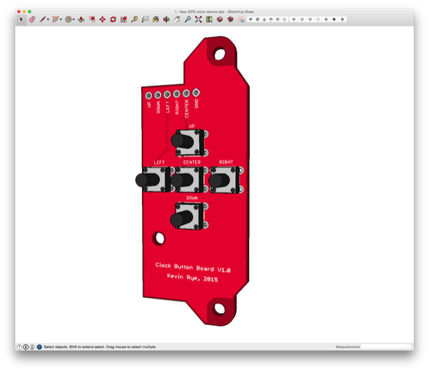
The button board will be mounted right on top of the existing PCB. I'll solder leads from the button board header directly to the pads on the clock PCB where the 5-way switch was.
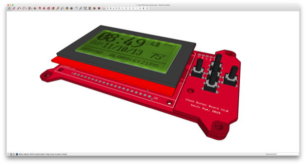
I then designed a new case to house the electronics. I tried my best to maintain the cool shape that the PCB had. I didn't want to just throw everything into a rectangular box.
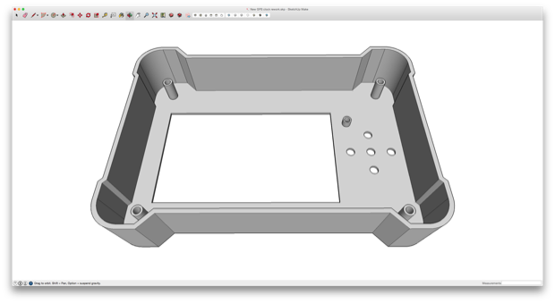
The PCB will then be screwed into some board stands on the inside of the enclosure.
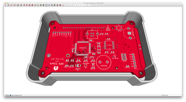
Rather than have a bunch of ugly screw heads on the back, I'm going to design the back cover so that the two pieces simply snap together.
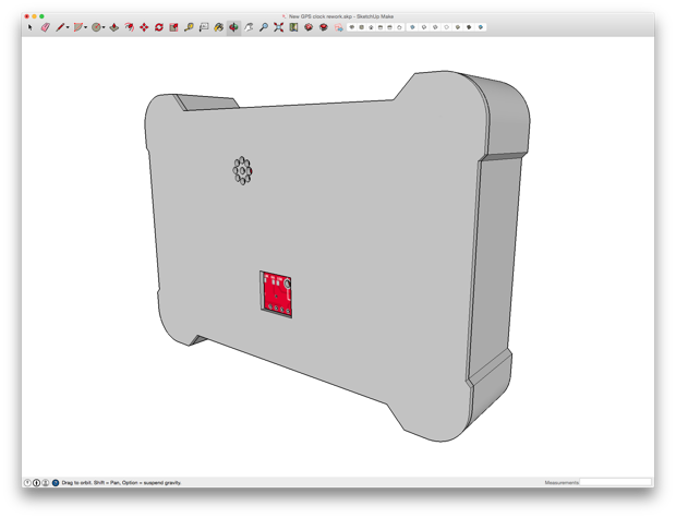
I want to print this one in gray, but I'll have to wait a day or two for the PLA that I ordered to arrive. In the meantime, I'm going to print the prototype in yellow.
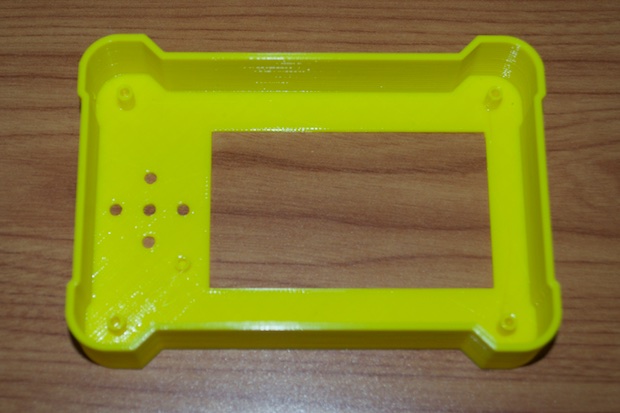
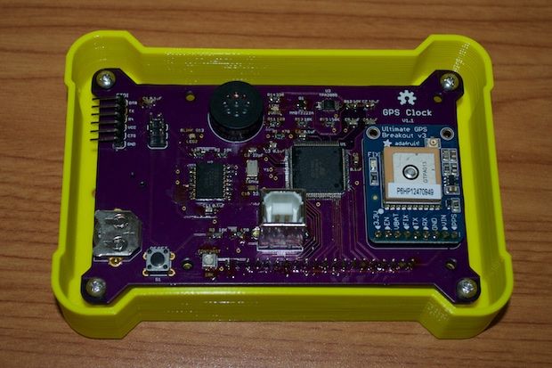
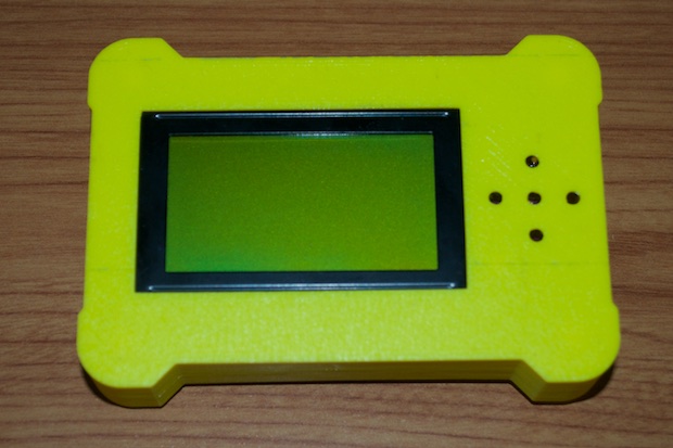
At first blush, I'm tempted to say I nailed it, but I won't know for sure until my button board PCB arrives. Even if I have the gray PLA in hand, I'm going to hold off on printing the final version until I can make sure that the buttons fit in the holes.
See this project from start to finish: GPS Clock Prototyping, Part I GPS Clock Prototyping, Part II Arduino Mega 2560 GPS Clock Prototyping, Part III GPS Clock Prototyping, Part IV GPS Clock Prototyping, Part V GPS Clock Assembly, Part I GPS Clock Assembly, Part II GPS Clock Assembly, Part III GPS Clock Assembly, Part IV GPS Clock Rework - Ditching the Joystick, Part I
GPS Clock Rework - Ditching the Joystick, Part II GPS Clock Rework - Ditching the Joystick, Part III


