I have all my parts. I have my PCBs. I have a new Dremel. It’s time to put this bad boy together!
I first have to start my trimming off the little tabs that remain on the PCBs from when they were broken apart.
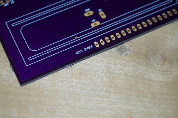
I just took my Dremel and gently rubbed them off until everything was flush.
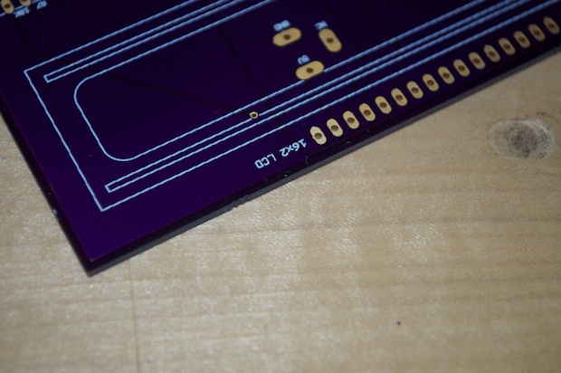
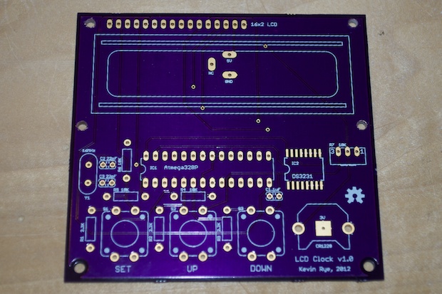
I never placed holes for the LCD in my Eagle file because they were too hard to line up without having a reliable way to verify them. I tried laying the LCD on a printout, but no matter how much I tweaked the location of the holes, they never looked right.
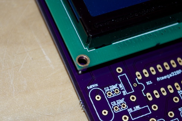
I opted to just drill them once I had the board. That way I know they’re be in the right location for sure.
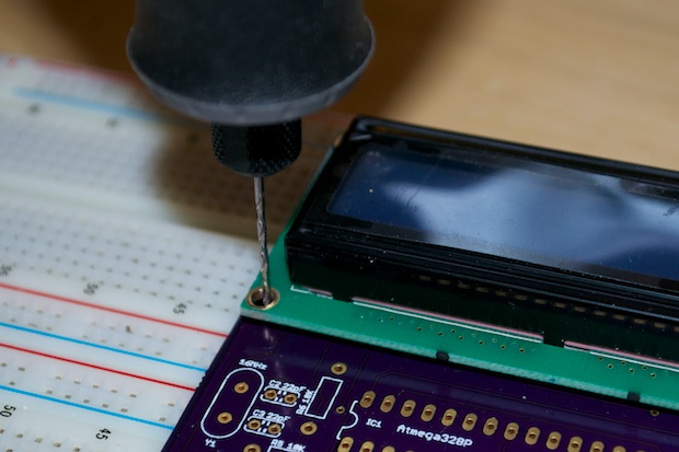
Perfect. Once the screws and nuts are in place, you won’t even be able to tell I drilled the board after the fact.
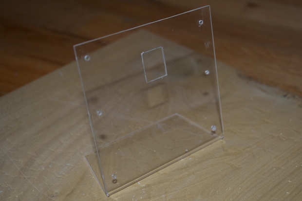
Once the holes were in, I could then lay the PCB on the acrylic stand and mark off the holes, and drill. I formed the rectangular hole for the power jack with a metal file.
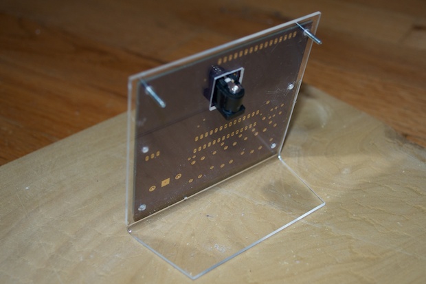
Once everything is put together, I’ll trim the screws. They are a little too long. I can’t finish it today since I can’t find the matching 4-40 nuts. I had to order some online since Home Depot, as well as the local hobby store, doesn’t carry them.
Now, to solder all the components. I figured I’d start with the DS3231 SMD chip. If I screw that up, then the board is toast. So I don’t want to screw it up after everything is already soldered in. Better to do it first and get it out of the way.
I first lined the chip up on the pads and used the “Fun-Tak to hold it in place “ trick.
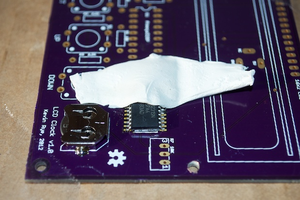
Once you’ve soldered a few pins, and the chip is firmly in place…
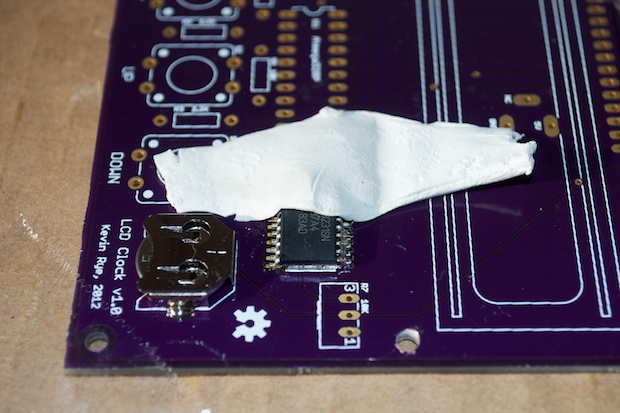
…it’s safe to remove the Fun-Tak and do the rest of the pins. I also soldered in the battery backup so that I could take my volt meter and make sure I had Vcc and ground on the appropriate pins. That way I know I have good connections on all the pins.
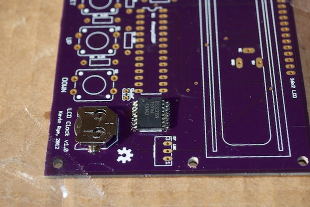
Not bad for my first SMD chip. I went ahead and soldered all the other parts onto the board.
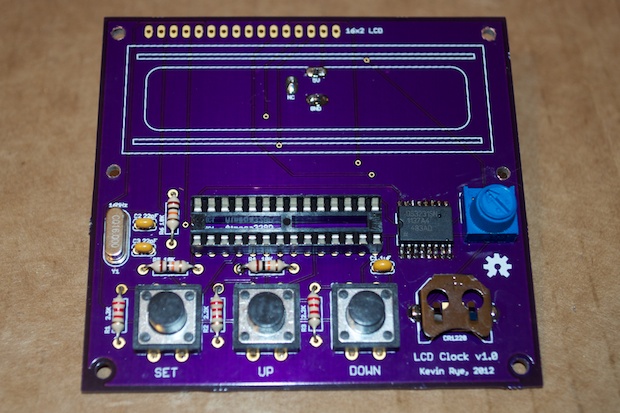
I had to make a conscious effort to remember to solder in the power jack before soldering the LCD. That would have been a nightmare of a rework to unsolder the 16-pin header.
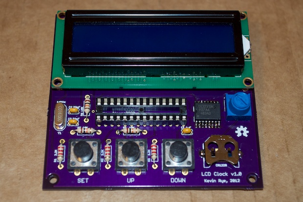
Good to go. It looks awesome. I’m really happy with the way it came out.
OK, let’s plug it in and cross our fingers!
Woo hoo! Success!
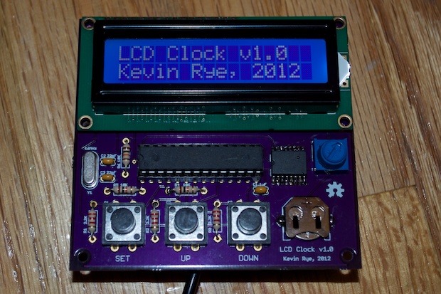
It works like a charm!
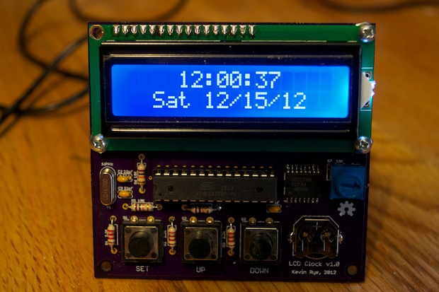
Knowing that the PCB design is good, it was safe to go ahead and assemble a second clock. I just had to
burn the bootloader to another ATmega, which was a little trickier than I thought. It worked out in the end. I used the red display that I picked up from SparkFun. It came out pretty nice.
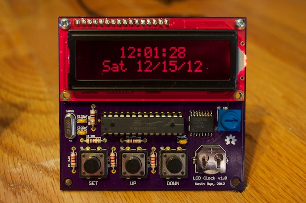
It’s not as bright as the blue display from Adafruit, but the digits look pretty cool in red.
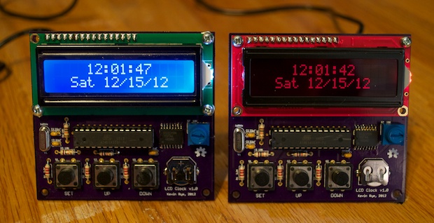
It’s awesome to see a month and a half of R&D pay off like this. Just think, a month and a half ago I never even had an Arduino. Now I’m designing PCBs, writing code, and making clocks!
I just have to
complete the stand and it’s on to the
Word Clock!
See this project from start to finish: We Have a Clock Setting the Clock Clock Code is Complete Clock Design Decisions New DS1307 Kit ChronoDot Breakout Board Arduino LCD Clock PCB Complete Making the LCD Clock Stand - Take 1 Arduino LCD Clock PCBs Arrived! Arduino LCD Clock Assembly
Making the LCD Clock Stand - Take 2 Another Clock Stand Arduino LCD Clock: New GUI Laser Cut LCD Clock Enclosure: Take 1 Laser Cut LCD Clock Enclosure: Take 2


