Laser Cut LCD Clock Enclosure: Take 2
May 26, 2013 Filed in:
Clocks | Laser CuttingIf you remember, the first attempt at getting a front panel laser cut for my LCD clock
didn’t work out so well. I don’t think it was a tolerancing issue. I think I just screwed it up.
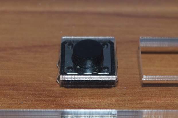
Although the holes cut for the LCD and the switches were spot-on, they weren’t where they were supposed to be.
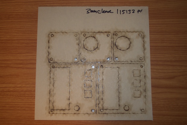
I tweaked the file...
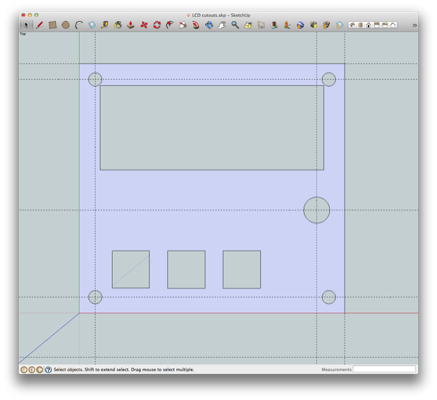
…converted it to SVG...
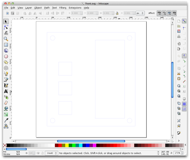
…and printed it out once more.
I also cut out a hole for the LCD potentiometer. I hadn’t cut out a hole on the last one since I didn’t think I’d ever need to tweak the contrast again. However, if I cut a hole out for it, I can push the acrylic that much closer to the PCB. That’ll bring the buttons closer to the acrylic, making it easier to press them.
Since I also wanted to make a front panel for the
SpeakJet board, I combined both files into one order and submitted them together. Having something laser-cut is really cheap; it just takes forever to have done. It was only $6.77 for the acrylic and the cutting, but it took 19 days to receive it!
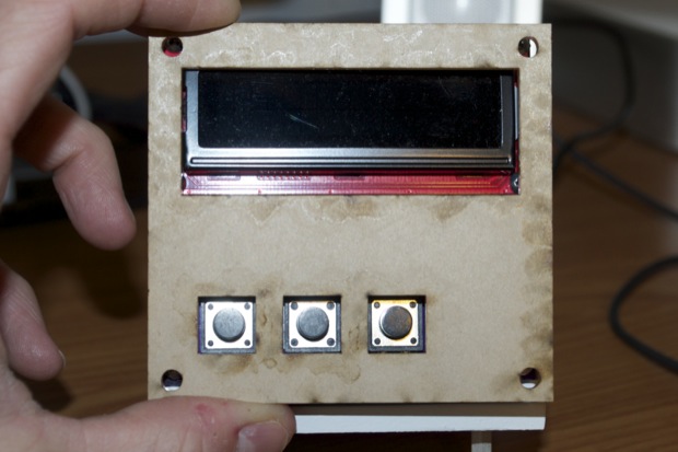
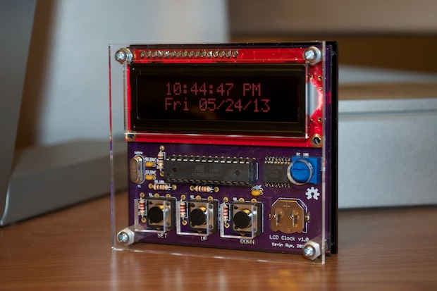
Ahhhh, that looks much better!
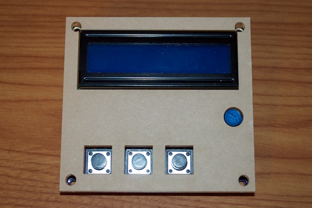
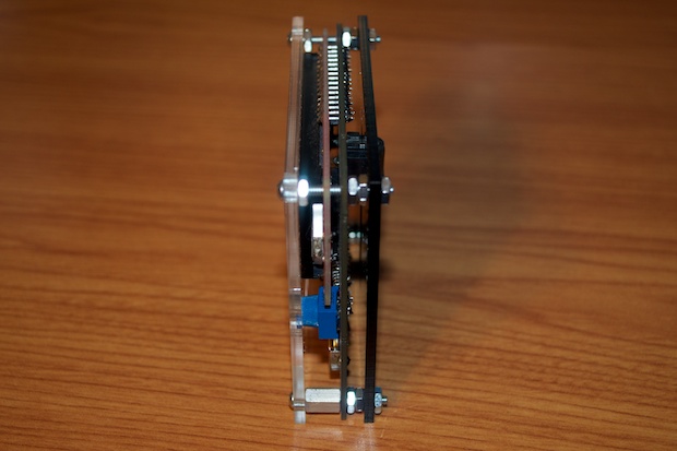
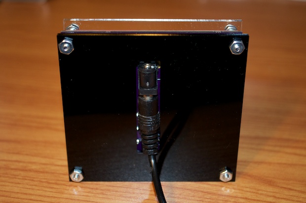
I used a few 1” screws, some standoffs, and some nuts to assemble everything together.
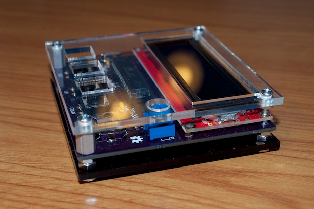
It looks awesome. It’s just like I pictured it 6 months ago a when I designed the clock. It’s great to see everything finally come together like this. I think this clock is finally done-done.
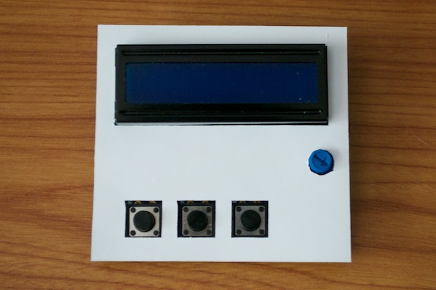
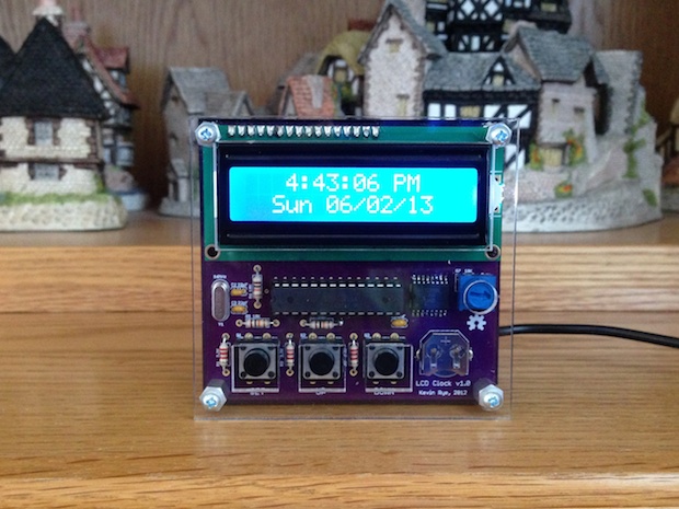
I sent the 2nd one to my Dad so he could also upgrade his clock. He sent me a picture so show me how it turned out: Awesome!
 See this project from start to finish: We Have a Clock Setting the Clock Clock Code is Complete Clock Design Decisions New DS1307 Kit ChronoDot Breakout Board Arduino LCD Clock PCB Complete Making the LCD Clock Stand - Take 1 Arduino LCD Clock PCBs Arrived! Arduino LCD Clock Assembly Making the LCD Clock Stand - Take 2 Another Clock Stand Arduino LCD Clock: New GUI Laser Cut LCD Clock Enclosure: Take 1
 Laser Cut LCD Clock Enclosure: Take 2

