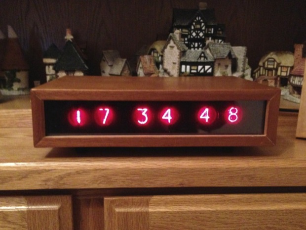
When I was a kid, my Dad showed me his nixie tube clock that he made back in the ‘70s using 7490 TTL chips. It’s awesome. (I had him send me a picture!)
Ever since then, I’ve been fascinated with clocks. I’ve always wanted to build a nixie clock. About 12 years ago I set out to build a clock of my own.
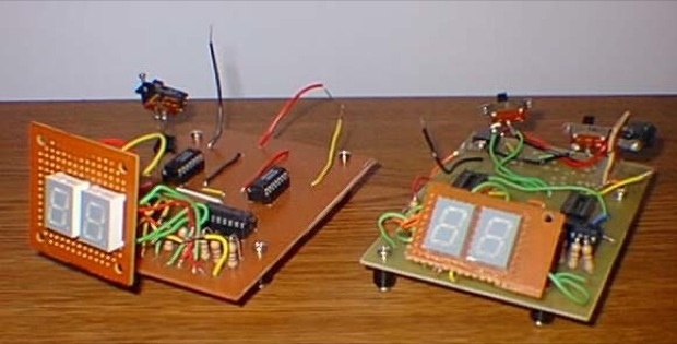
I figured I’d start out small with a few prototypes. I made a few boards, experimenting with different sections for the seconds, minutes, and hours. (Sorry about the lousy pics, but they were taken in 2001 with a 1996 EPSON 1MB PhotoPC digital camera. It captured mages at 640x480. Hey, what do you want for $500?)
When I was happy with the results,
I made a full sized clock incorporating all that I had learned.
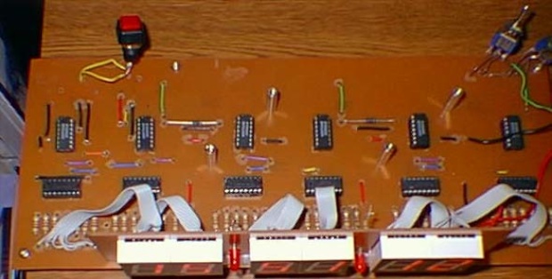
Although it wasn’t a nixie clock, and the project box I used was huge, I was happy with the results. I chose to use 7-segment displays since I was a little weary about messing around with the high voltage required for nixies.
During my research, I found that no one was really using 7490s anymore. Counting cycles was old-school. I guess that was the only way to do it “back in the day”. It was crude, but effective. People nowadays were using micro controllers. I found a ton of schematics for clocks running off a single chip. Even the clocks around the house that I had, when cracked open, revealed that they too only used one chip. How do they do it?
As I researched more, I found out what was involved. I’d need a chip burner if I was to make one of my own. This was years before the advent of Arduino, so chip burners were expensive. You could build your own, but the cost was prohibitive. I didn’t even know if I could get one to work. Also, I knew nothing of programming and didn’t even know where to start. Looking at the programs written in C seemed so foreign to me and I just couldn’t get my head around it.
I quickly became discouraged and never pursued it any further.
Back in 2007, I broke my iPod. I wanted to buy a new 5G Video, but I didn’t have the money. I though of maybe picking up an iPod Shuffle in the interim. I also considered building my own mp3 player. I’ve always been fascinated with the ability to encode/decode audio through a chip and save it to a hard drive or a solid state chip. I wondered what it would take to make one of my own. I’d seen a few people online do it, but again, all done with those confusing microcontrollers. People were now using these new-fangled open-source Arduino boards. I couldn’t figure it out. Again, I was discouraged.
I bought an iPod Shuffle.
Fast forward 5 years.
Now that I’m an avid
iOS developer, I have a few years of programming under my belt. I looked back into embedded electronics and rediscovered Arduino. Seeing some sketches written in C I couldn’t believe how easy it was. I grabbed an
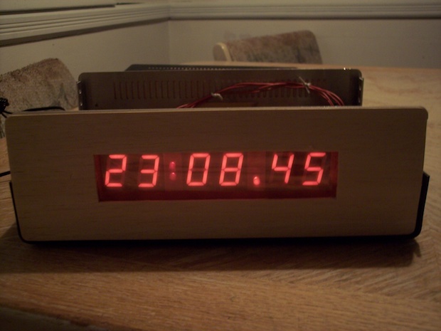
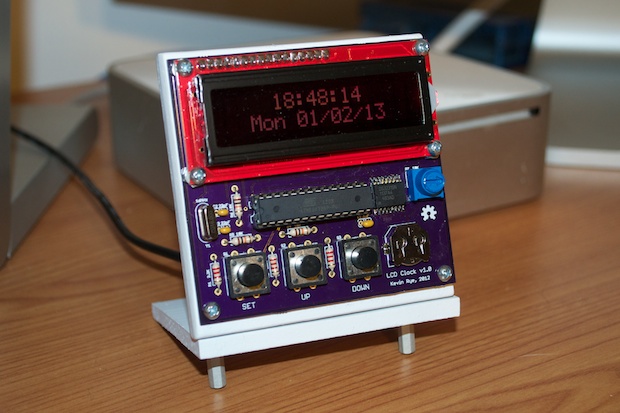
Arduino board and got right to it. It took me a day to get my feet wet. A few days later, I had a fully operational
clock prototype.
With Christmas around the corner, I thought that the first clock based on a microcontroller that I built would make an excellent present for my Dad, since he’s the one that inspired my interest in electronics. I finished up the clock just in time. All I needed to do was build a stand for it.
I made a stand and was very happy with the way it came out. I gave the clock to my Dad for Christmas. He loved it.

I took some time off after the holidays. Once everyone had retuned home, I had some free time to work on some projects. I got to work on making myself a stand for my clock.
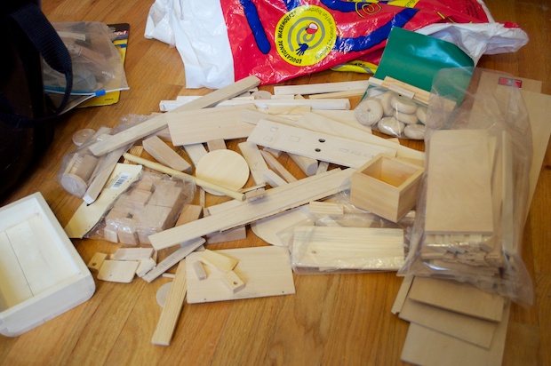
I rummaged through my bag of wooden scraps to look for something suitable.
I found this little box left over from when I made my
own iPod dock back in 2006.
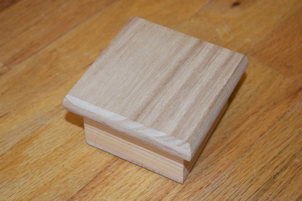
The lid looks to be the perfect size.
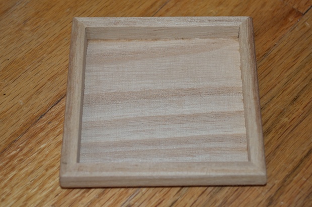
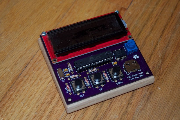
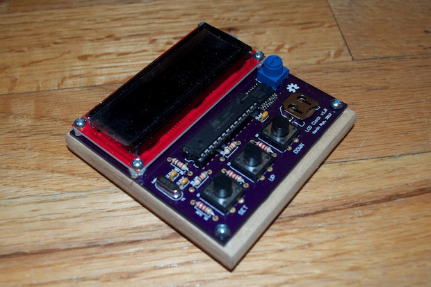
I laid the clock PCB on top and it is a good fit. However, the screws wont’t go all the way to the bottom. I won’t be able to screw nuts onto the backs of the screws. I can just hot glue them in.
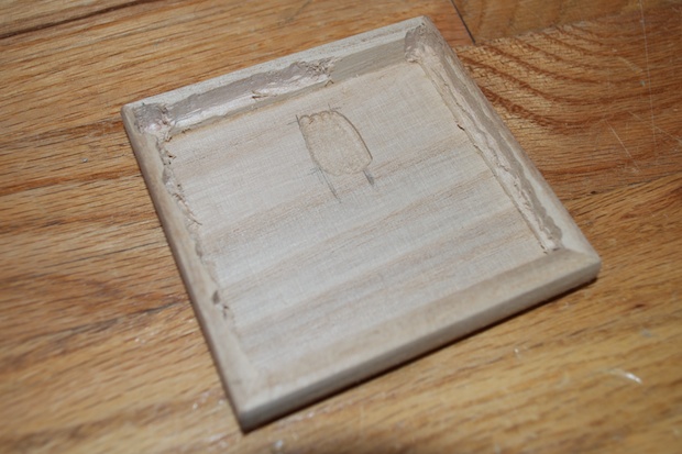
I used my handy-dandy new Dremel Workstation to cut out enough space for the screws.
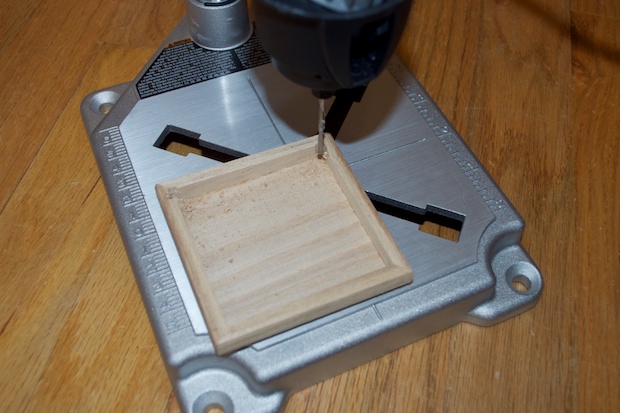
I also had to route out a little portion in the middle so that the DC jack would fit. It’s not pretty, but you won’t see any of it once the clock is glued in.
I sat the clock on top once again. It’s a perfect fit.
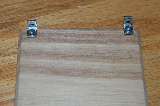
I then screwed some L brackets to the back so that I can attached it to the base.
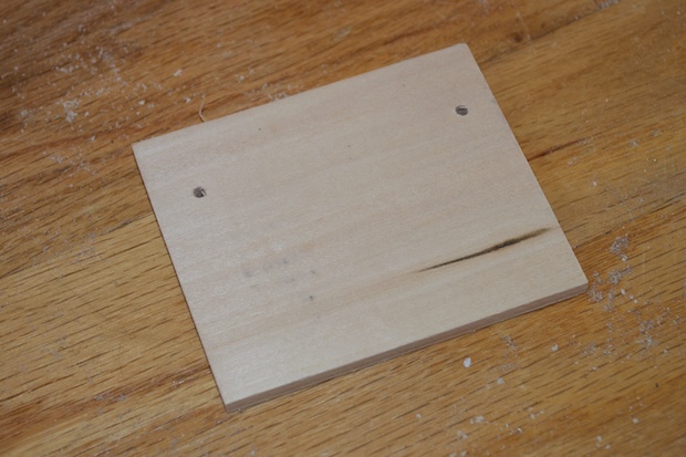
I picked out a piece of wood, marked it off, and cut it to size.
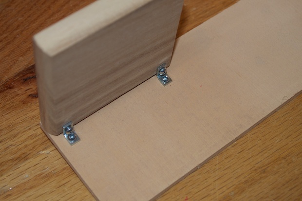
I then drilled some holes through it for the L brackets.
I screwed some board stands to the bottom.
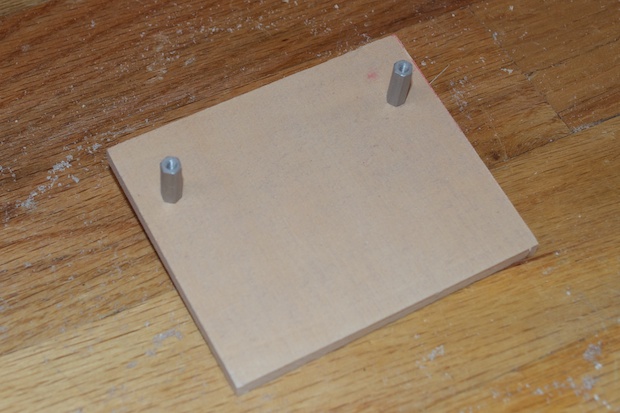
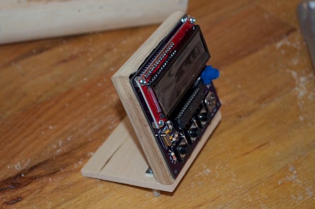
It gives the clock just enough lift so that the display sits at an angle from the viewer. It also helps it from tipping forward.
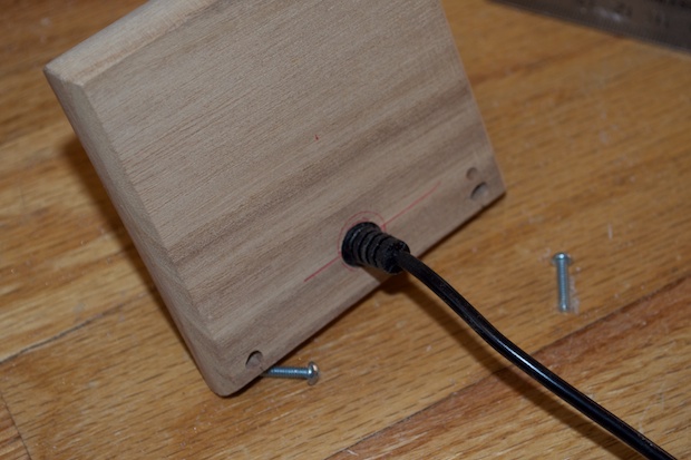
I then drilled a hole in the back large enough to snake the power cord through.
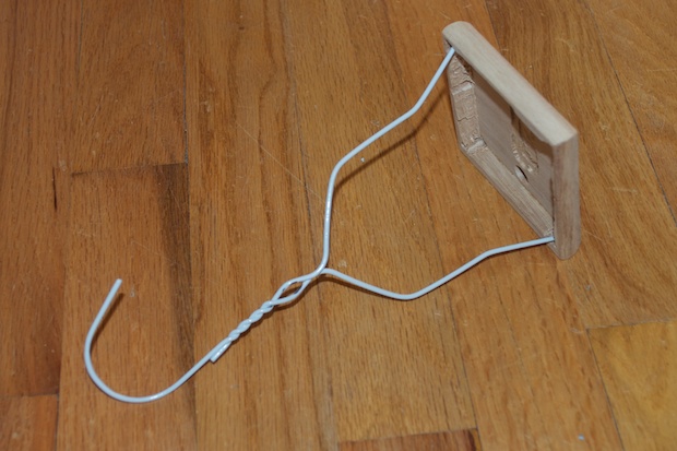
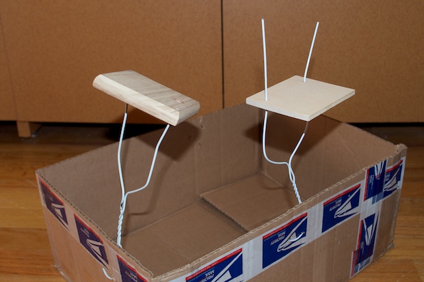
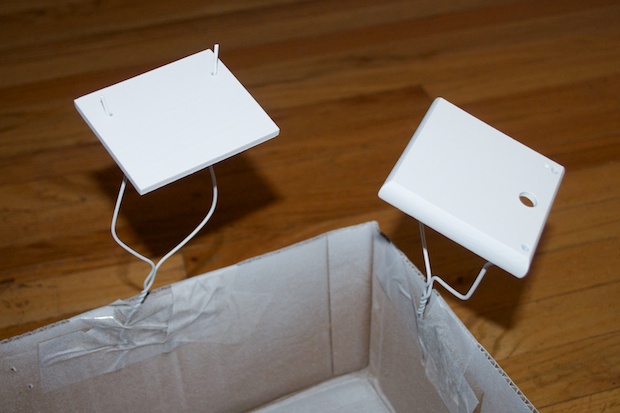
I then cut up some coat hangers to serve as makeshift painting stands.
I taped them to a box and took them outside to be painted.
I gave them a few coats of primer….
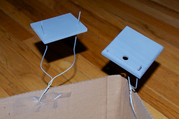
…followed by some white.
All that was left to do was glue the clock in with my hot glue gun and it was good to go. I like the way this one came out.
 See this project from start to finish: We Have a Clock Setting the Clock Clock Code is Complete Clock Design Decisions New DS1307 Kit ChronoDot Breakout Board Arduino LCD Clock PCB Complete Making the LCD Clock Stand - Take 1 Arduino LCD Clock PCBs Arrived! Arduino LCD Clock Assembly Making the LCD Clock Stand - Take 2
 Another Clock Stand
Arduino LCD Clock: New GUI Laser Cut LCD Clock Enclosure: Take 1 Laser Cut LCD Clock Enclosure: Take 2
