This clock prototype is getting pretty big. I need three breadboards to lay everything out, and I still need to add the audio stuff. It's getting pretty messy and since they're sitting on my computer desk, it's getting pretty hard to sit in front of the keyboard.
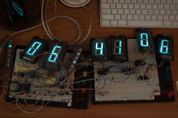
I decided to relocate it to one of my kids' small little fold-up tables to make my life easier. I also took the opportunity to completely rewire the whole clock to maximum the board routing that I'll have to do on the PCB. With the primary hardware pretty much nailed down and the time displaying properly, it was time to push on with the rest of the code.
The good thing about making a lot of clocks is that after a while, writing the code becomes a bunch of cutting and pasting. The code for this clock closely mirrors that of both of my
nixie clocks as well as my
LCD clock. I just had to make a few small tweaks. After about two hours, I had all the code written for the time mode, date mode, and alarm mode.
In Time Mode, a colon is displayed between the hours, minutes, and seconds. (The ILT1-5 L I ordered for the minutes/seconds colon still has not arrived in the mail yet. For now we'll just pretend it's there.) A PM indicator is also displayed, as appropriate.
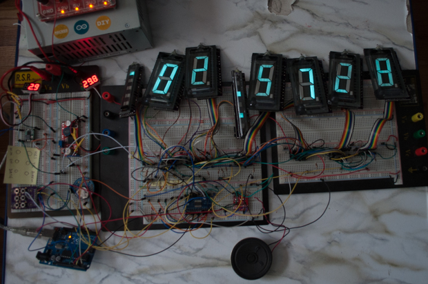
Pressing the Date Mode button displays the date. The PM indicator is turned off, as well as the top colon indicator. Pressing the Data Mode button again puts you back in Time Mode.
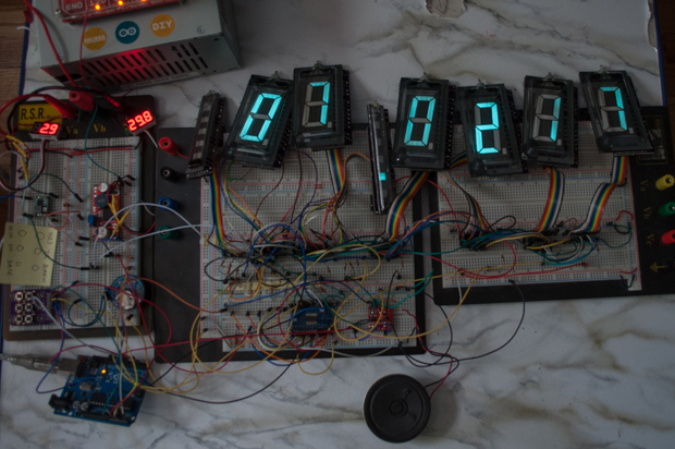
Pressing the Alarm button puts the clock in alarm mode. I turn on another indicator under the PM indicator to let you know you're in alarm mode.
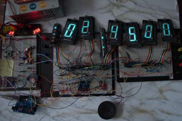
Pressing the Alarm Enable button toggles the alarm on/off. You can enable/disable the alarm in any mode. Another indicator is displayed under PM to let you know that the alarm is enabled.
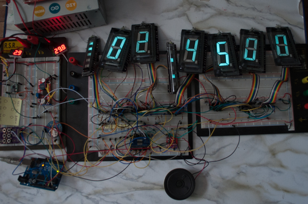
I still have to make some tweaks to the alarm code since the "delay" that's in there interferes with the multiplexing. I'll probably have to change that to a "while" loop. In any case, here it is for now. It goes off for 20 seconds.
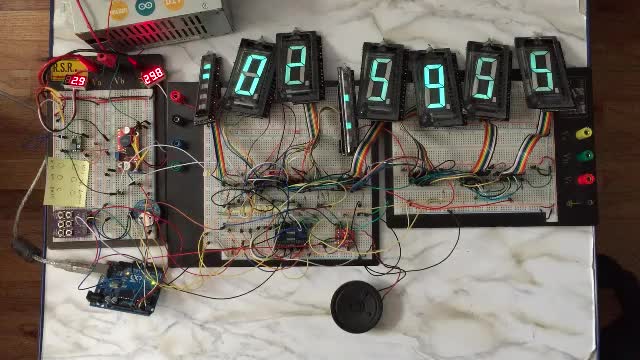
I designed a little
AC Filament Driver board, but I'm not sure yet how I want to implement it in the final build, or if I will at all. I nailed down a PCB with what I have so far. It's looking pretty good. It's going to be huge, and expensive. So I have to make sure everything is perfect. There's nothing worse than throwing a $70 board in the trash.
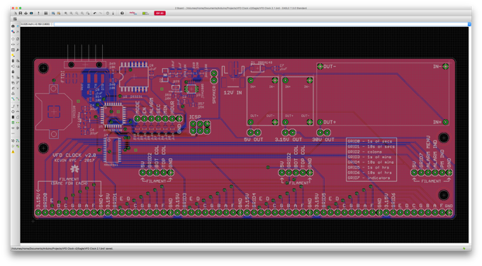
I wasn't originally going to mount the boost converter on the board, since I thought that would mean that the board would have to be bigger than it needs to be, but the 60-pin header that I need to connect the displays is pretty much dictating the width of the board. I had the space, so I figured I'd throw it in.
See this project from start to finish:
More VFDs!!! VFD Breakouts Large VFD Clock - Part I VFD AC Filament Driver Large VFD Clock - Part II
VFD AC Filament Driver V1.1 Large VFD Clock - Part III Large VFD Clock - Part IV Large VFD Clock - Part V


