I took a break from the VFD Clock to make a
Portal Weighted Storage Cube. That took about a month, and now that it's finished, it's time to revisit the clock. I left off with making some
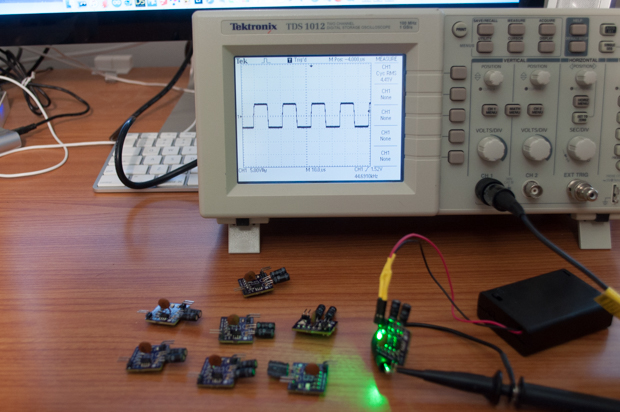
VFD AC Filament Drivers. They looked pretty good after connecting them to my scope, but they're a bust. I don't like the way that they work at all. They just don't put out enough juice to power the displays. They're just too faint for my liking. I don't think it's my design, I think the 3V regulator I'm using doesn't put out enough juice to power 9 hungry VFDs. I'll have to revisit this another day, for now I just want to push on. I'll just power the filaments with DC. Since the displays aren't connected together, there shouldn't be any noticeable decay in brightness across the entire display.
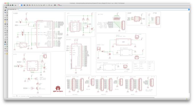
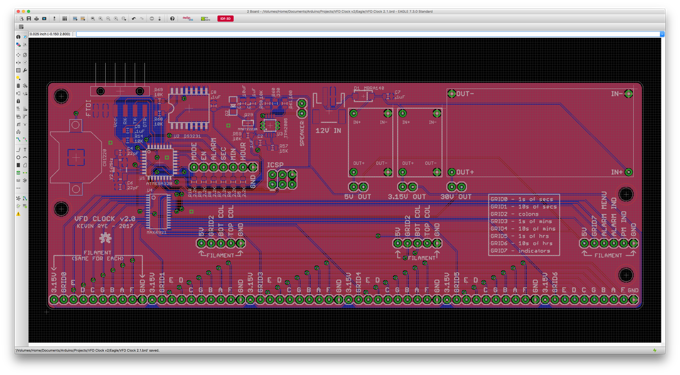
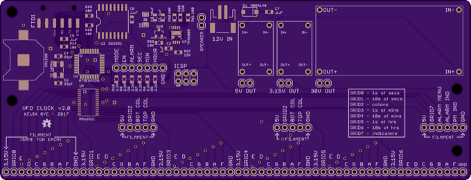
I finalized the schematic and the PCB.
It's looking really good. It's a pretty big board. It cost $70 bucks to get them from OSH Park.
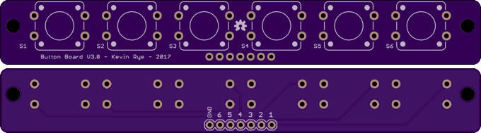
I also made a new button board. I was going to just use one of the left overs from the last
VFD Clock, but I needed 6 buttons this time.
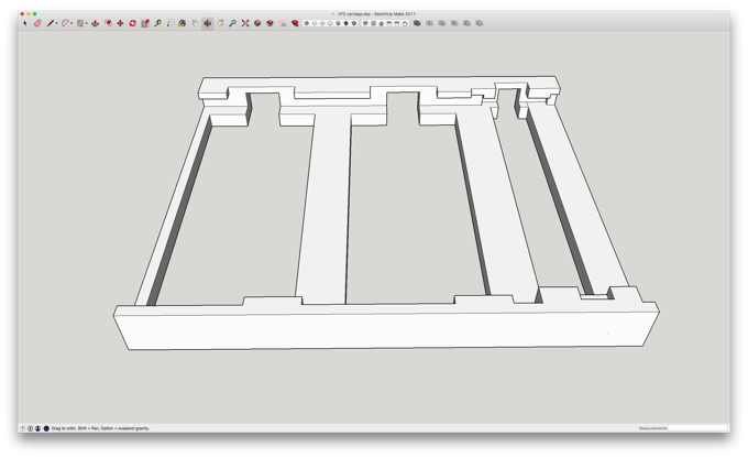
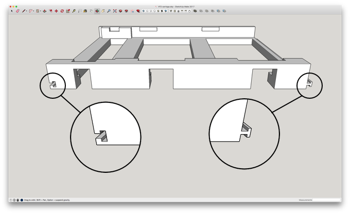
While the PCBs were being made, I got to work on a 3D-printed chassis for the displays. I first started out by just trying to nail something down that a display could clip into. Nothing fancy, just enough to figure out the dimensions.
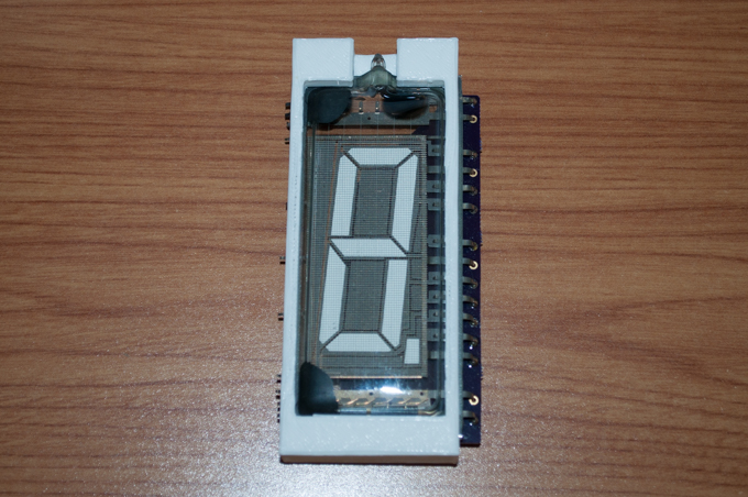
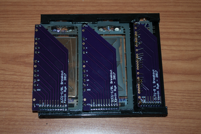
The display just clips into the back. No glue or screws required.
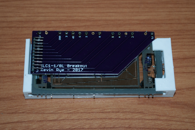
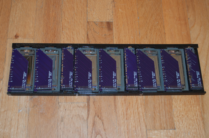
This one was a little more difficult since the header on the PCB is right at the edge of the display.

There was no PCB for me to clip onto. The display is basically held in with a tight fit. I might put a blob of hot glue over by the header just to stop the display from falling out.
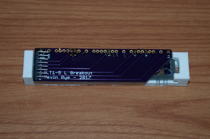
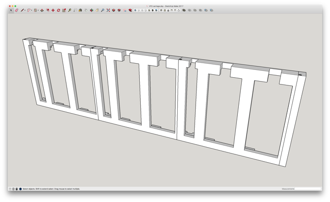
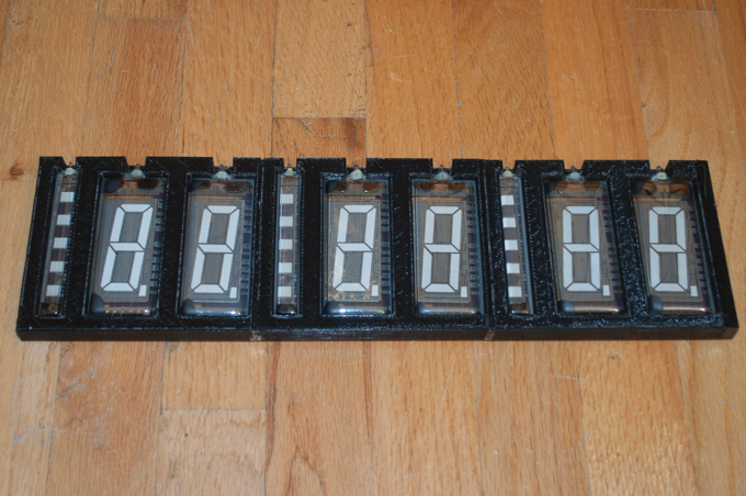
I then took those two designs and combined them into one assembly.
That looks cool…
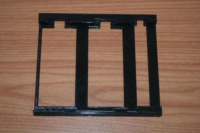
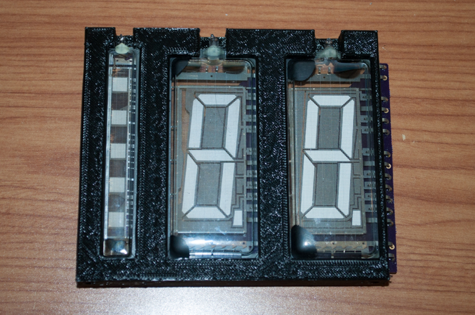
..and everything fits perfectly.
That looks really cool.
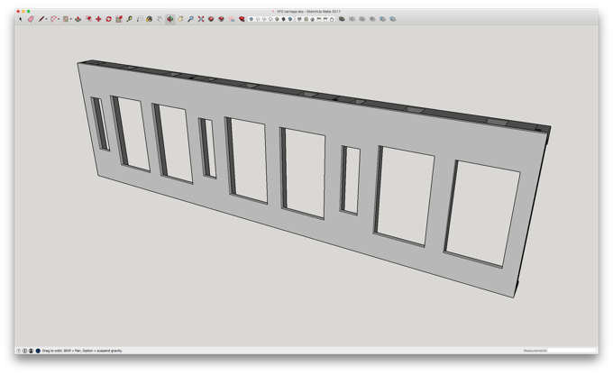
I was just going to print another two sections and epoxy them together, but they have a little bit of weight to them. I don't think glue is going to do the trick. I decided to incorporate some interlocking connectors on the ends.
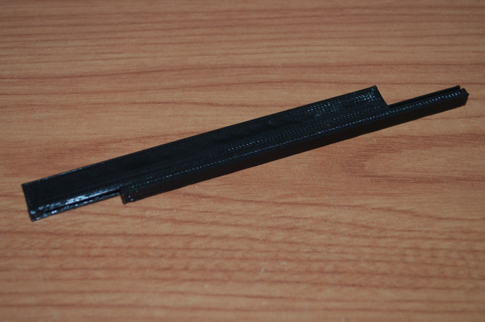
The pieces will just slide together at the ends.
I printed one of each end type just to make sure that they slide into each other.
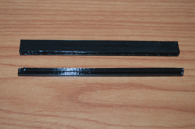
They slide tighter perfectly with a nice tight fit.
I then printed three new sections and slid the pieces into each other. It's solid.
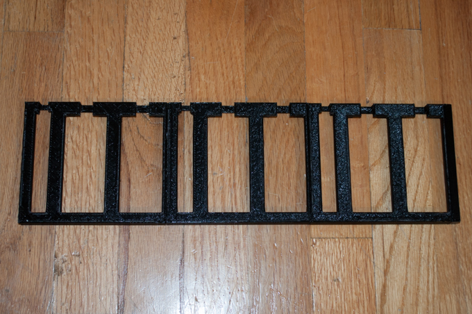
That's awesome. The PCB will be mounted on the back with something I have yet to design.
I'll probably then get some kind of panel laser cut for the front.
More to come…
See this project from start to finish:
More VFDs!!! VFD Breakouts Large VFD Clock - Part I VFD AC Filament Driver Large VFD Clock - Part II VFD AC Filament Driver V1.1 Large VFD Clock - Part III
Large VFD Clock - Part IV Large VFD Clock - Part V
