With all the prototyping complete, it was time to put together a PCB. I spent a couple of days making sure everything was perfect and then sent it off to be fabbed.
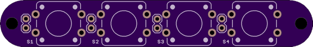
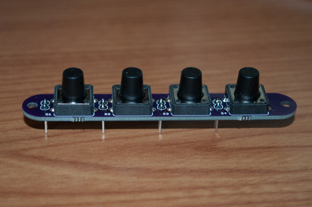
I was going to use the same button board that I used in my
Nixie and
LCD clocks, but I decided to make a new one with larger 12mm buttons.
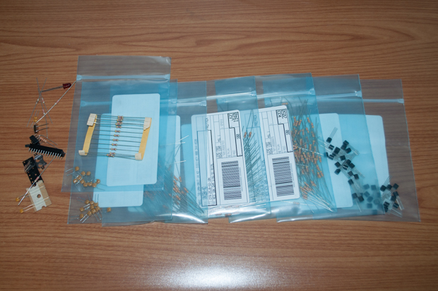
While I waited for the boards to arrive, I ordered my components.
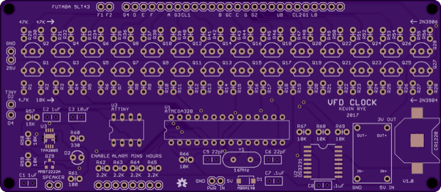
A few days later, my PCBs arrived. This is going to be an awesome build! Look how huge this board is!
I first started with the ATmega328, the DS3231, and supporting components. I then uploaded the blink sketch just to make sure that it worked.
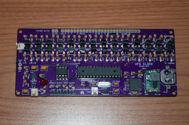
With that tested, it was time to put everything else together. Normally I test things as I go, but I'm pretty confident I got everything right. That looks like a lot of components, but surprisinglt, it's only 362 solder points.
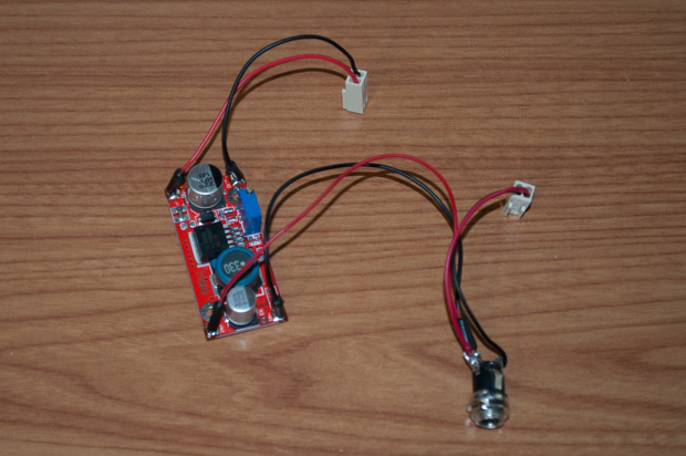
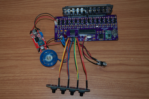
I then put together the power supply. It has two connectors: one for 25 volts and another for 5 volts. The 5 volts comes right off the DC input jack. I'm using a regulated 5 volt wall wart, so I don't need to have another regulator on the PCB.
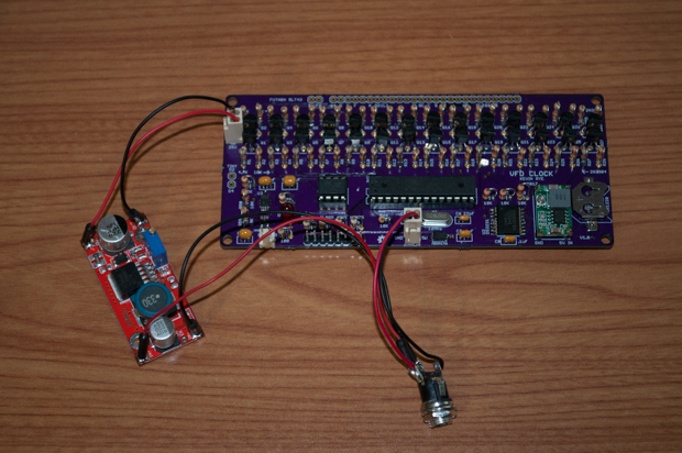
I then connected it to the PCB. I kept the power supply external to the PCB this time, and easily replaceable with the use of 2-pin connectors. I learned my mistake from the nixie clock that I build. I incorporated the power supply into the PCB as a daughter board. When that power supply blew, it was a real pain to unsolder it from the board. If this $4 boost converter dies, it'll be super easy to replace it.
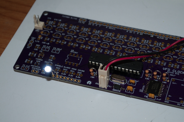
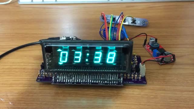
OK, I'm pretty confident I got everything right, but still….I'm no fool. I don't want to solder the display on and then find out the clock doesn't work. So, I just inserted the display into the holes and powered it on. Sweet! It works!
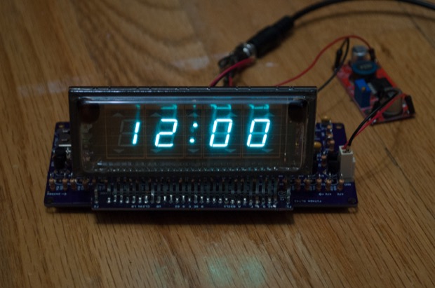
Knowing that everything was OK, I soldered the display in place. I then got to work on the speaker and the buttons.
For the buttons, I soldered in a few 2-pin headers and 4 large buttons. I needed to use some tall ones so that even if I 3D print a 3mm thick enclosure, the buttons will still stick out the top.
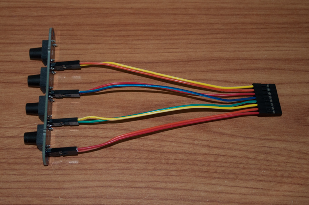
I made a ribbon cable that has an 8-pin Dupont connector on one end and four 2-pins on the other. I like making things modular. It makes future upgrades and repairs super easy.
I then connected the speaker and the buttons to the PCB.
All done. I'm so pleased that everything worked on the first go without any tweaks. I really double checked everything before sending the board out. When boards cost $60 to have them fabbed, there's no room for mistakes. Add in the cost of the components and this could have easily been a $100 dry run.
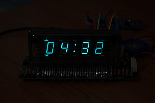
Here's the alarm in action:
It's a lot louder in person, and the display looks so much better than it does in the video. It's really hard to take a picture of it. The display comes out better with a faster shutter speed.
Now to get to work on the enclosure. I started it almost a month ago, but I couldn't finish it until the clock was actually built.
See this project from start to finish:
I Finally Figured Out This Vacuum Fluorescent Display VFD Clock - Part I VFD Clock - Part II VFD Clock - Part III VFD Clock - Part IV
VFD Clock - Part V VFD Clock - Part VI Clock Button Panels
