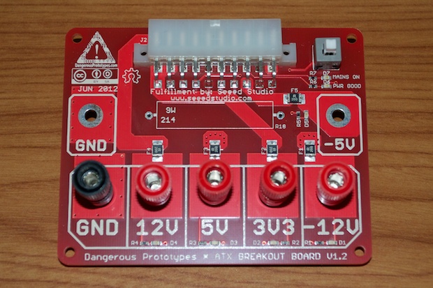
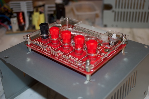
Finally! After waiting 3 weeks for my ATX Breakout Board to arrive, I can get to work on my DIY bench-top power supply.
This is the ATX Breakout Board designed by
Dangerous Prototypes.
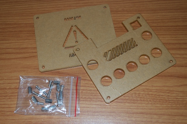
The acrylic case was only $4 bucks. I’ll be screwing the breakout board directly to the power supply chassis, so I won’t be needing the bottom panel.
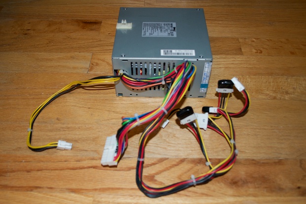
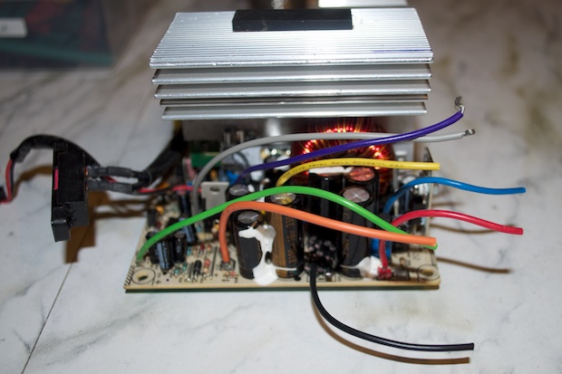
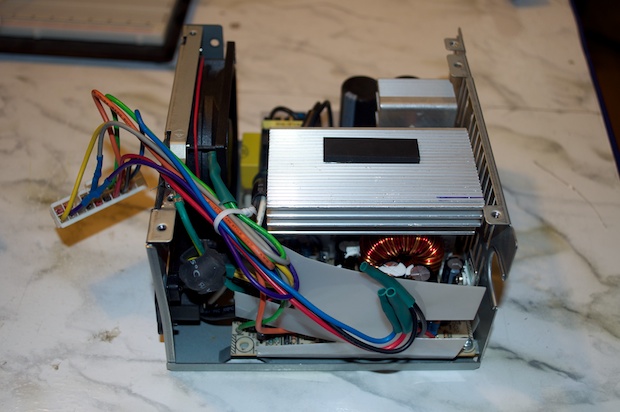
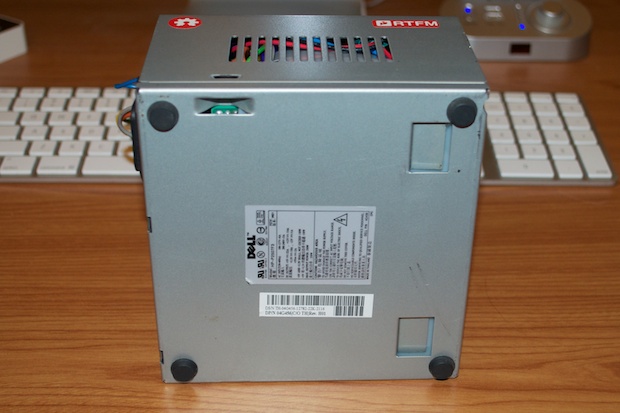
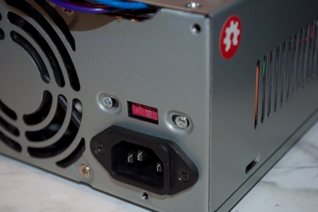
Here is the 250W power supply I pulled from my friend’s
dead Dell. As you can see, it’ll need some work if it’s to be made into a bench-top power supply. The AC input is on the back, but all the wires come out the front. That’s not an ideal configuration for what I want it for. I want to mount the ATX Breakout Board right on the top, so all the wires will need to come from the back. I’ll have to rework the case and the wires in order to clean things up. I only need the wires that are connected to the 20-pin ATX connector. All the cables that usually go to drives and fans won’t be needed.
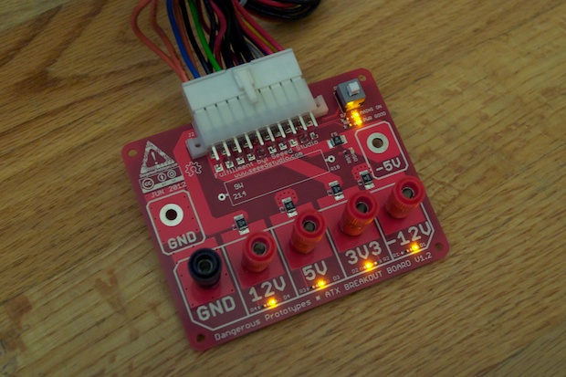
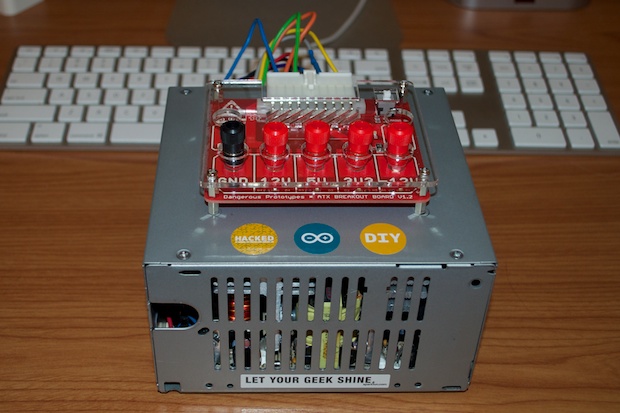
Just to make sure that the board worked before I started hacking away, I plugged it in and powered it on. Looks good.
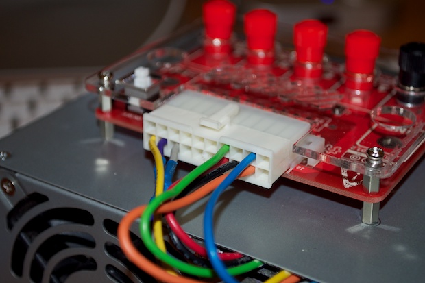
Looking at the schematic, it’s clear that all the 3.3V, 5V, and ground connections are tied together. The PG (power good), 5VSB (mains status), -12V and -5V connections are also broken out.
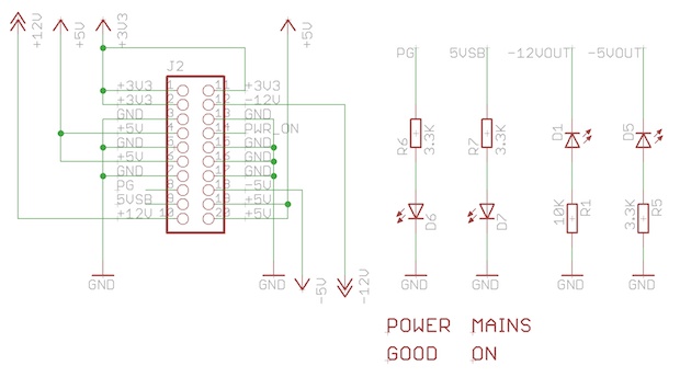
Of the 20 wires on the connector, I only really need 8. I can safely cut the other 12 off and everything will still work. Well, 11 actually. My power supply doesn’t have a -5V output. That’s common on modern power supplies. That’s why the -5V port on the breakout isn’t populated.
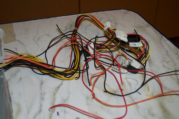
I cut away all the wires, just leaving the 8 that I needed.
That gets rid of a nice bulk of unnecessary cables.
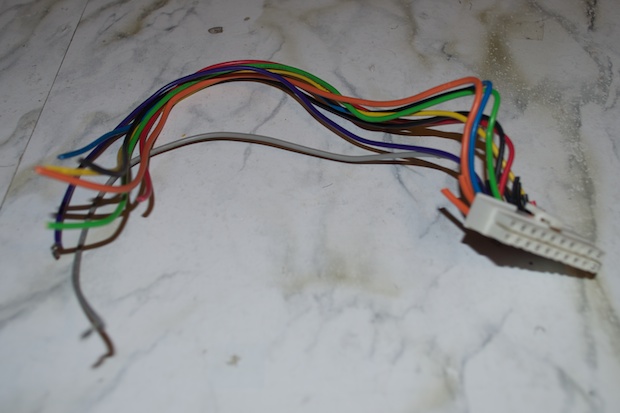
Also, the 20-pin connector doesn’t need to be that long either. It’s going to come right out of the back and into the breakout. It’s safe to trim off a good 4 inches, eliminating even more bulk.
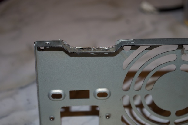
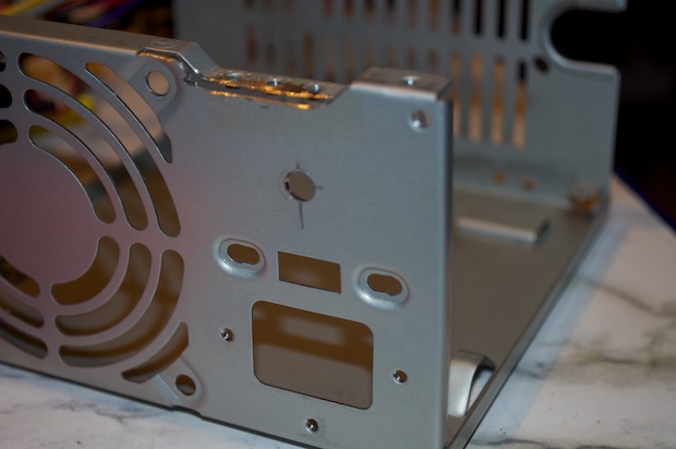
In order to re-route the cables out the back instead of the front, I needed to Dremel away a small portion on the back.
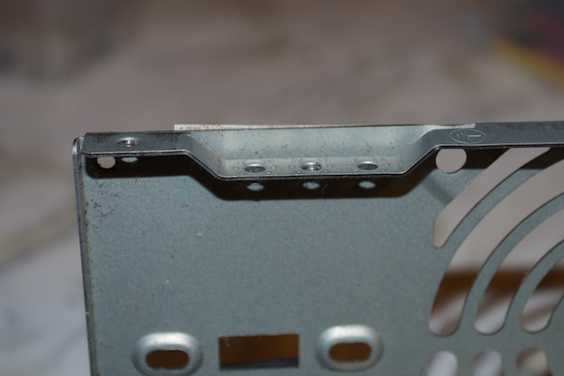
Perfect. I should be able to sneak the 8 wires out the back without it looking too messy. I thought about just cutting a rectangle in the top of the case and snaking the ATX connector out there, but I only have one shot at this, so I’m erring on the side of caution.
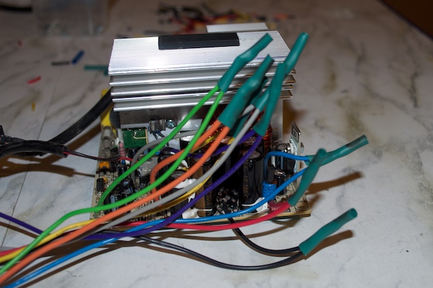
I then soldered on my now-shorter ATX connector and shielded the connections with heat shrink tubing.
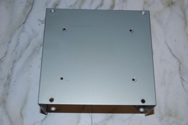
For the top, I peeled off the stickers and relocated them to the bottom. I marked off where the breakout board will go and drilled the holes.
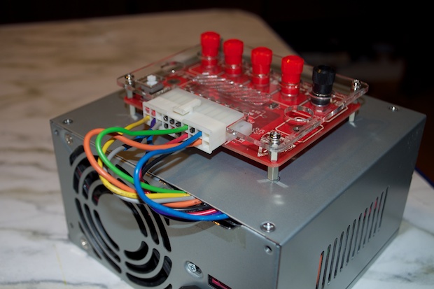
I screwed on the standoffs from the underside...
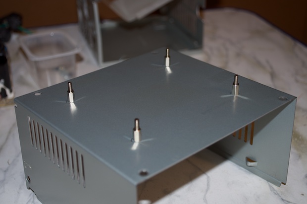
...and then finished mounting the breakout board.
One strange thing that I noticed is that the fan no longer comes on. It spins really, really slow at first and then stops. I don’t know if it has something to do with all the wires I cut off, or if it’s because there’s no load attached. I failed to notice when I first plugged the breakout board in if the fan spun at full speed or not.
Once I button everything up, the wires (with all that extra heat shrink tubing) will be running in the opposite direction that they used to. They’ll touch the heatsink unless I find a way to tie them down and out of the way.
My concern is that if the fan no longer works, the heatsink might get hot enough to melt the wires and/or heat shrink tubing.
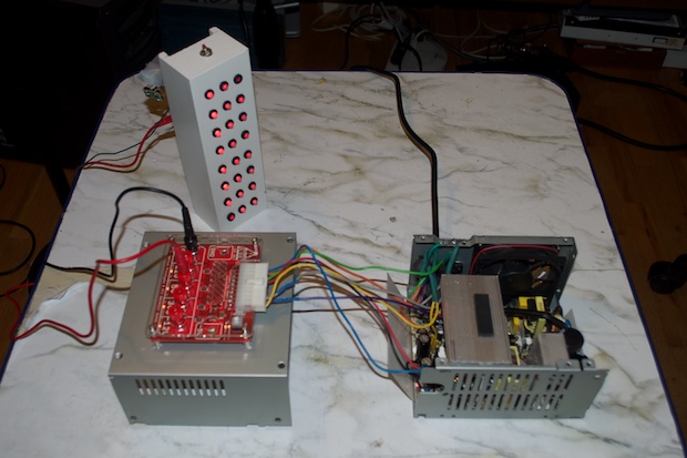
In order to see how hot this thing gets, I connected my old
RGB LED Nightlight. I let it sit for 2 hours. The smaller heatsink on the right was pretty hot, but that’s not a problem since it doesn’t come in contact with any wires. The larger heatsink on the left is the one I’m concerned with, but it was only slightly warm. It’s probably not a problem, but I was still not convinced. My nightlight is only sucking 500 mA or so. Most of my Arduino projects are very low power, but I figured I’d try something else just to make sure.
I connected my
GPS Clock prototype. It uses a pretty beefy display, an Arduino Mega, a Chronodot, an Adafruit Ultimate GPS module, and an audio amplifier breakout. It should suck a little more juice than a handful of LEDs.
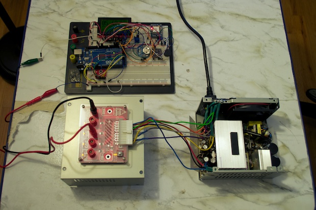
I let it run for a few more hours. Same results. The heatsink is barely warm. In any case, I took some measures with twisty ties in order to keep the cables as far away from the heatsink as possible.
I ran the wires out the back and screwed the top back on.
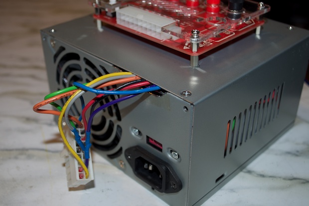
I then plugged in the breakout board. I clipped the leads on the ATX connector as close to the connector as I could, but I thought it looked kind of ugly.
In order to get the pins out, you need one of these handy-dandy pin-extractor tools. That, or a really tiny flathead screwdriver that you can get in their with to bend the retaining clips inwards.
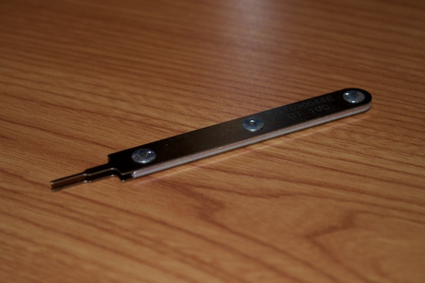
Much better. Much cleaner.
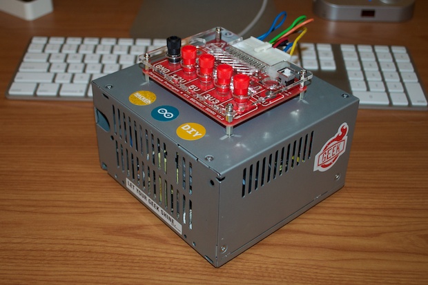
For the finishing touch, I put some rubber feet on the bottom...
...and decorated it with some geeky tech stickers.
But I couldn’t leave well-enough alone. That fan was really bothering me. Not so much from a safety standpoint, but more so because that fan’s going to work because I SAID SO!!! I’m not one to lie down and let the tech tell me what it’s not going to do.
If the power supply won’t turn the fan on, I will. I’ll run 12V right to it. I don’t want the fan on all the time. That might get annoying listening to it all day. As I proved, the power supply doesn’t get all that hot, but I don’t know what I’ll be hooking up to it in the future. I might just need a little more cooling than the heatsink can provide. It would be nice to have a switch that I can flick to turn the fan on when I want.
This looks like a pretty good spot for a switch.
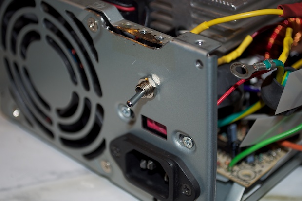
I took the whole thing apart and drilled a hole for a switch.
I then cut the fan’s 12V lead loose from the PCB and soldered it to a toggle switch.
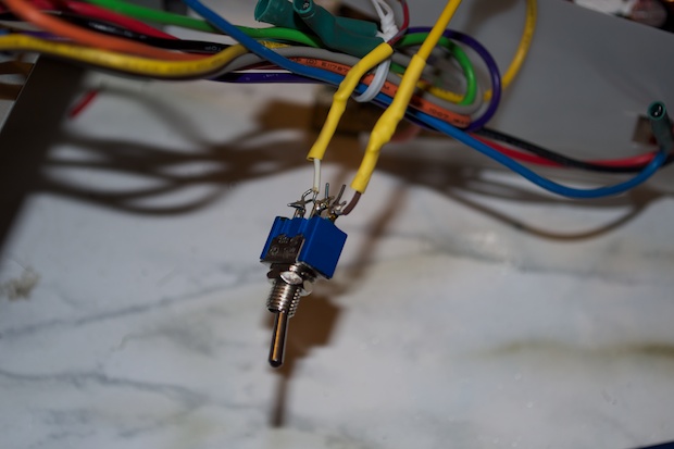
That should do the trick.
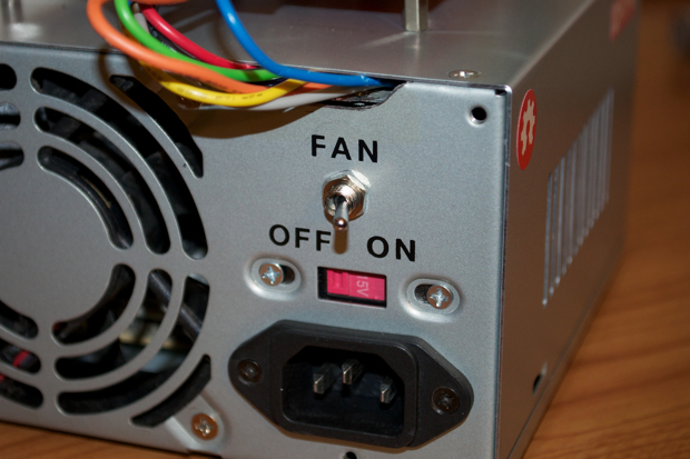
I then put the whole thing back together again. I used some rub-on transfer labels to put some text on the back.
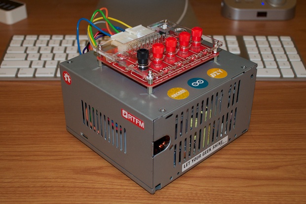
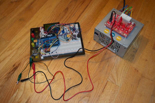
And there it is in action. I just need to order some banana-to-banana leads so I can connect it directly to my breadboard. The ones I have are either banana-to-alligator clip or banana-to-test probe.
With the exception of the breakout board, the whole idea was to build this thing for zero dollars. Ideally, I’d wrap those wires in the back with a nice braided sleeve, or do away with the chassis and put the guts in a custom laser-cut black enclosure. The problem with that is, the acrylic would probably cost a good $30 bucks. With the additional bells and whistles needed, the final cost could hit a good $60 bucks. For that, I’d sooner go out and buy a better looking power supply.
I really like the way it came out. It’s going to come in especially handy with all the upcoming nixie projects I have in mind. I’m going to get a lot of use out of it.
See this project from start to finish:
Bench-Top Power Supply, Part 1 Bench-Top Power Supply, Part 2

