As I mentioned in my
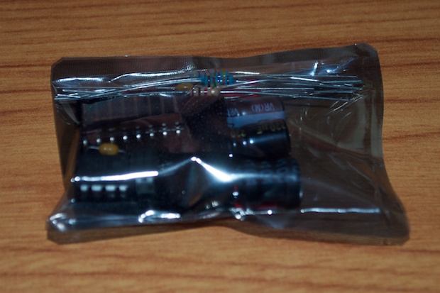
previous post, I picked up a new nixie power supply kit since the one I scored off my Dad was either toast, or defective. There’s no shortage of choices when it comes to nixie power supplies, so I basically picked one that was inexpensive (but not super-cheap) and in the US. There’s a lot available overseas, but I didn’t feel like waiting a month to get one. The one I ordered off eBay was only $9.45 and arrived in 4 days.
It’s a pretty easy looking kit.
It’s all through-hole components. I should have this soldered together in no time.
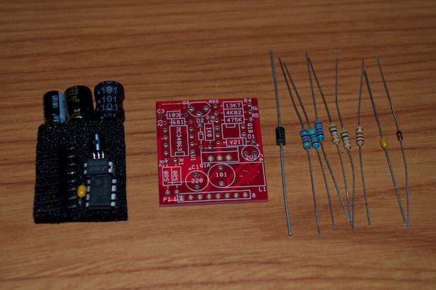
The great thing too about being a kit is that I can take some nice closeups of the PCB in case I want to incorporate the PC design into my own schematic. It looks fairly easy to reverse-engineer a schematic.

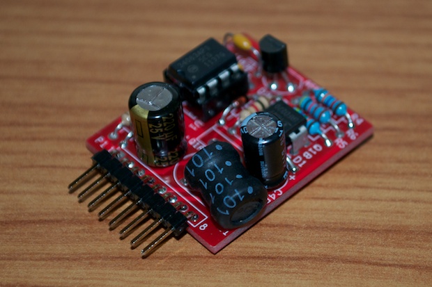
I took my time soldering it together. There was no room for error since I don’t have replacements for most of these parts. It took me about half an hour to put it together.
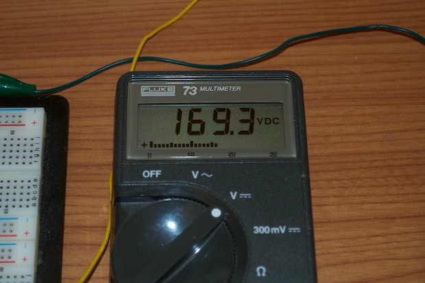
I connected it to my breadboard along with my DMM to monitor the voltage.
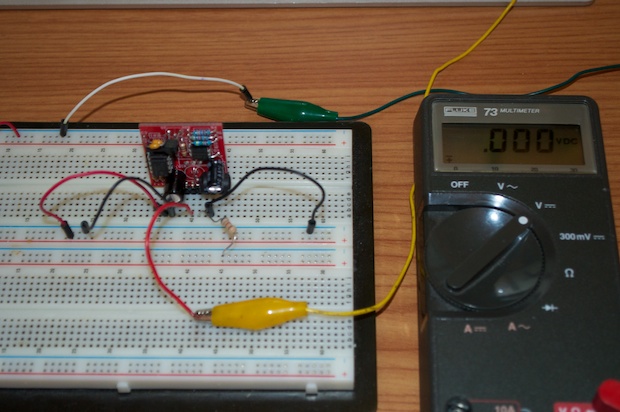
I then fired it up. 12 volts in, 170 volts out. Boom!
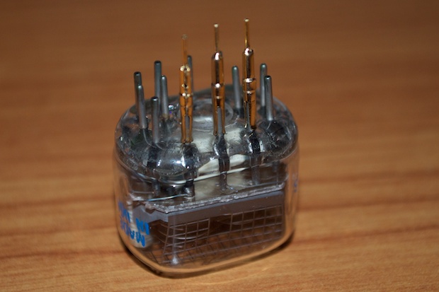
The socket pins I ordered from eBay also arrived in record time. All the way from the UK to the US in 6 days!
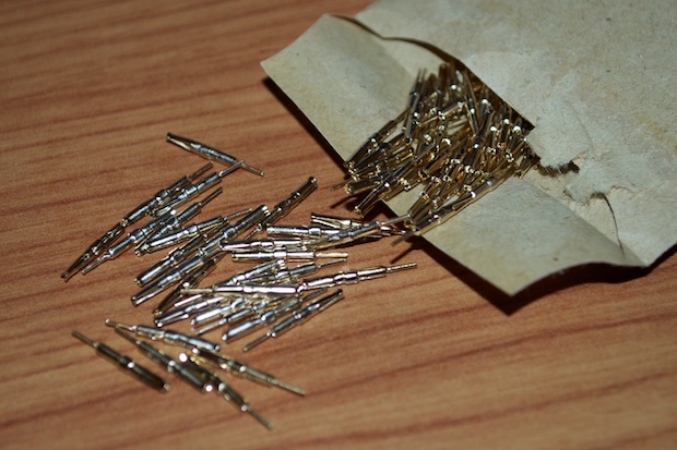
They’re pretty cool. They just slide right on. They’ll really come in handy when my
breakout PCBs arrive.
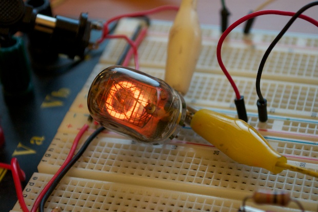
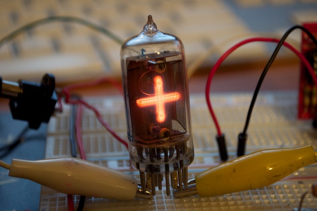
For some reason, I don’t seem to have either a 27K or 33K resistor. The insanity! I had to connect 3 x 10K resistors in series to the anode. I then connected 170V and grounded the “9” pin.
Ohhhh yeaaah!!!! It only took me a decade, but I finally got one of these nixies fired up!
I also have some NL-843s. I can’t remember exactly why I bought these, but they were around the same time as when I bought the IN-12s. Maybe even earlier. So I’ve had them for well over 10 years. In any case, I think they were so cheap that I bought them as an impulse buy in the event I also came across some IN-14s. Since the NL-843s only display a plus or minus symbol, I thought they might make for a cool colon substitute for a clock. Either that, or I ordered IN-14s and the dude sent me the wrong ones.
Whatever the case, it’s a nixie. And it looks awesome!
I’m still waiting for my PCBs to arrive so I can start prototyping with the IN-12s. I can’t wait!
See this project from start to finish: Nixies! Got My Nixies Powered!
IN-12 Nixie Breakout Board, Part 1 Flashing a Nixie with an Arduino IN-12 Nixie Breakout Board, Part 2 Driving a Nixie with a 74141 BCD Decoder More Nixie Tube Experiments Nixie Clock 5V / 12V Power Supply Nixie Clock PCBs / EAGLE Upgrade Nixie Clock Main Board PCB Build Nixie Clock Final Build, Part I Nixie Clock Final Build, Part II Nixie Clock Final Build, Part III Clock Button Panels
