I've been struggling trying to make the PCBs since EAGLE limits the board size on the free version to 100mm x 80mm. I have to make everything modular. That means one board for the power supply, one for the audio stuff, one for all the logic, and 3 each for the nixies and the drivers. 5 PCB designs, 9 boards in all. They'll all have to be clipped together with wires and headers, etc. Not to mention, OSH Park gives you 3 PCBs per order, so I'll have 6 PCBs left over. I'm sure I could use them in other projects, but the whole thing seems less than ideal.
I got pretty far with them, but I think it's time to cut my losses.
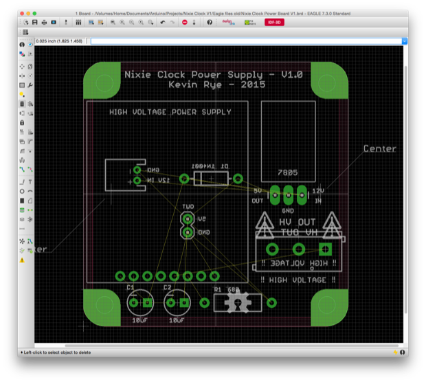
The power board:
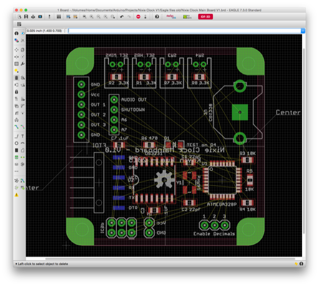
The main board:
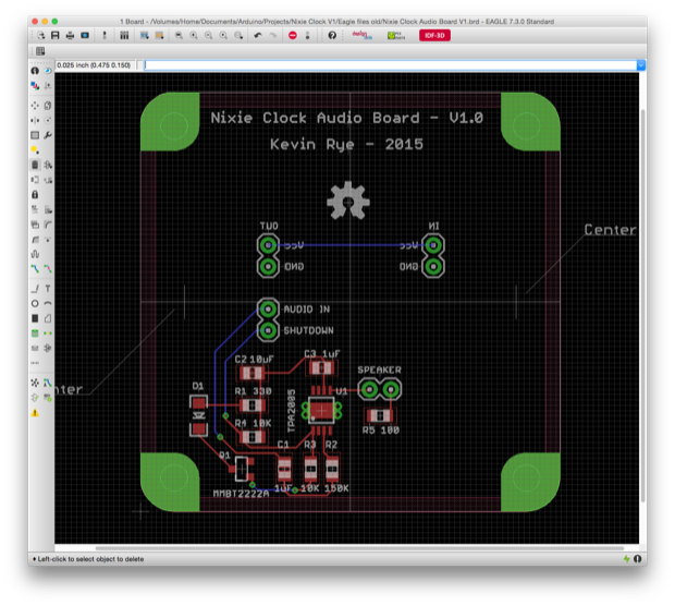
The audio board:
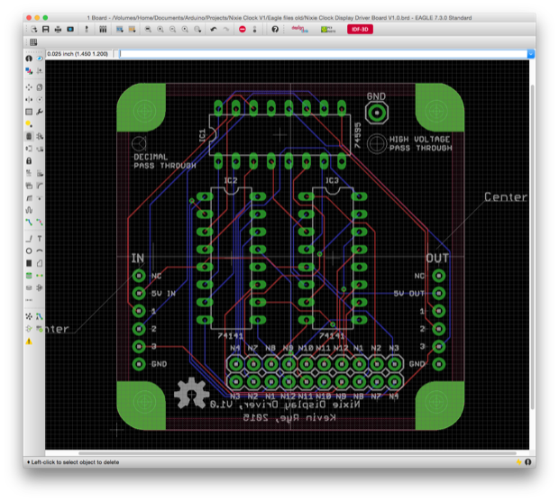
The driver/shift register board:
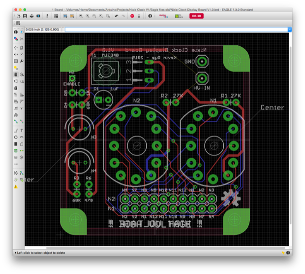
The display board:
I ran traces on 3 of the 5 PCBs and even chalked up somewhat of a block diagram that details how everything is connected together. I didn't want to miss any connections.
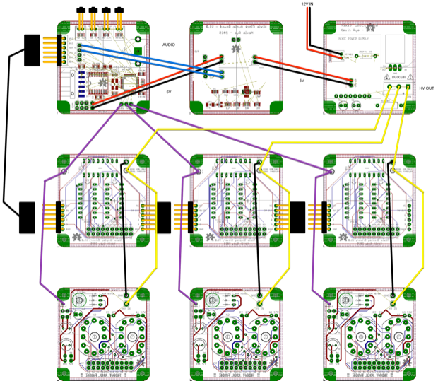
The end result would look something like this. The model doesn't have the audio and power boards, but you can see where I was going with the design.
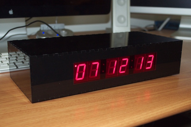
The approach is similar to that of the
large 7-segment clock that I just completed. I couldn't fit 6 displays and the colons on one board so I had to make several modules and mount them together on a 3D-printed frame.
The approach worked out well for that clock, but the nixie clock is way more complicated.
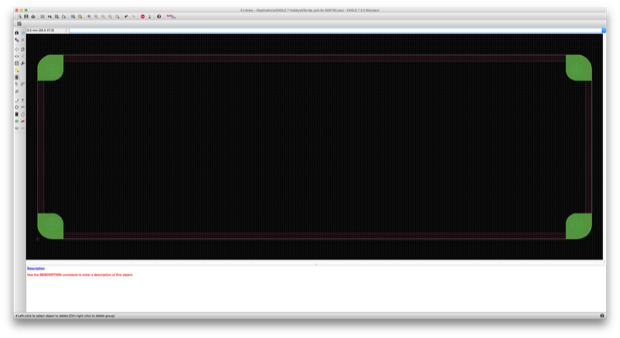
As you can see, I made the PCB modules as small as I could in order to keep the overall size of the clock as small as possible. The yellow frame shows the 100mm x 80mm board limitation of the free version of EAGLE.
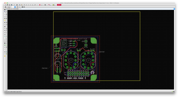
Push come to shove, I could fit 2 modules within that space, but not three.
I wanted to be able to just make one big board. I know I can’t make the entire clock one giant PCB. It’ll have to be at least 3 "layers" stacked up, but not made out of 9 separate boards.
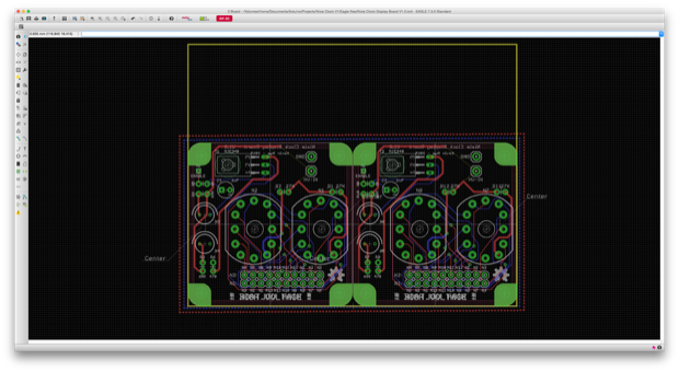
I bit the bullet and paid the $169 upgrade fee to the EAGLE Hobbyist version. It allows 160mm x 100mm PCBs. What a difference! Now I can make PCBs that are 6.29” long!
Now I can make one big board for the power, logic, and audio. Now I don't have to clip everything together. I'll also save some money on lowering the part count. Some of those connectors are $1 a piece!
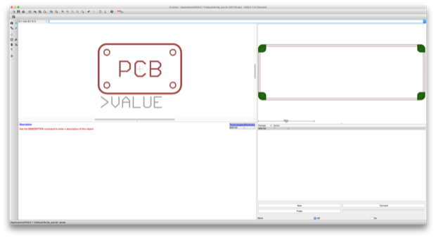
I created a new 150mm x 50mm PCB footprint modeled after
Dangerous Prototypes' Sick of Beige cases.
Awesome.
As a test, I pasted in my layout for the display board and moved one of the nixies to the far-side of the board. What a sigh of relief it was to not be met with the dreaded "Some objects extend outside the allowed board area." error message.
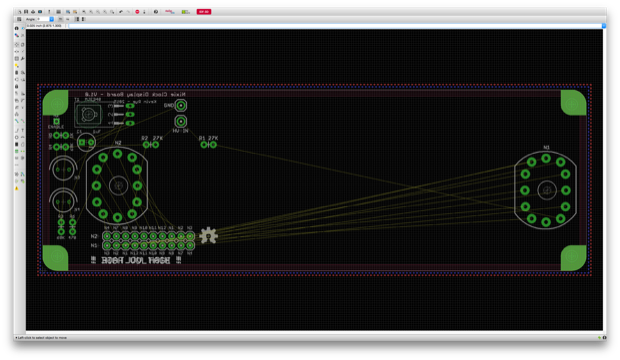
Anyway, I'm jumping the gun with the display board. I want to put together the main board first. Boom!
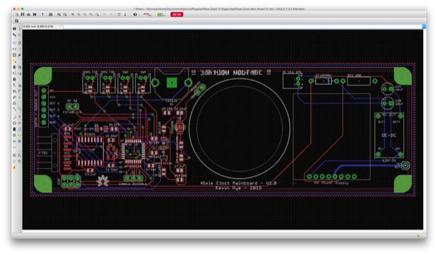
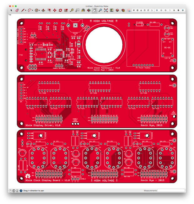
Logic on the left with the audio amplifier, a cutout in the center for a speaker, and the power stuff on the right; complete with my new buck converter.
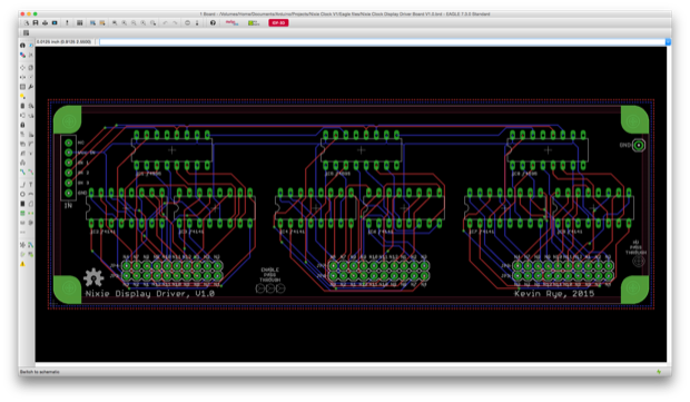
A PCB for the drivers and the shift registers. I actually have a bunch of wasted space on this board now, but it needs to be that same size as the others so that I can stack them.
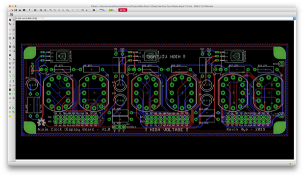
Finally, the display board. I'm thrilled that I managed to fit everything on one PCB. I didn't even have to use the entire 160mm length, so it's nice to know I have another 10mm to play with.
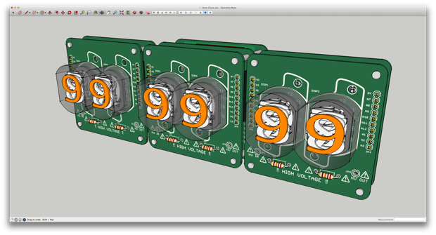
In order to make sure that everything would fit together as intended with enough clearance, I chalked up a 3D model. I first exported the boards from EAGLE to SketchUp.
I then created and positioned all the necessary components. I tried my best to draw everything to scale; for the ones that matter anyway. Some of the other components are just "graphical representations".
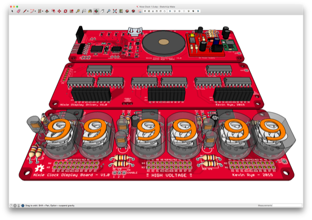
I then put it all together. Looks pretty good. It'll just be a matter of finding the right board stands.
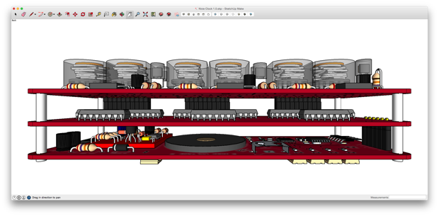
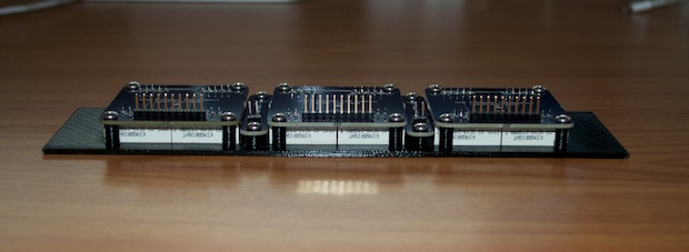
The boards sit 11mm apart. I though that it was an odd size for a board stand, but Digi-Key seems to carry them. Worst-case-scenario, I'll just 3D print something of my own like I did on the
Large 7-Segment Clock.
Now it's just matter of coming up with $189 bucks to order them.
See this project from start to finish: Nixies! Got My Nixies Powered! IN-12 Nixie Breakout Board, Part 1 Flashing a Nixie with an Arduino IN-12 Nixie Breakout Board, Part 2 Driving a Nixie with a 74141 BCD Decoder More Nixie Tube Experiments Nixie Clock 5V / 12V Power Supply Nixie Clock PCBs / EAGLE Upgrade
Nixie Clock Main Board PCB Build Nixie Clock Final Build, Part I Nixie Clock Final Build, Part II Nixie Clock Final Build, Part III Clock Button Panels
