IN-12 Nixie Breakout Board, Part 2
Oct 02, 2014 Filed in:
Electronics | Nixies | PCBsRev 1 of my
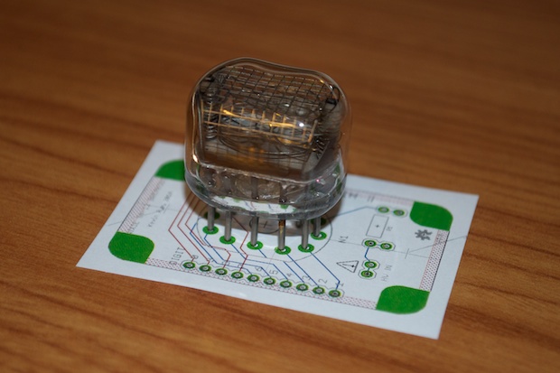
IN-12 Nixie Breakout Board was an abomination. Upon realizing that the nixie footprint that I used for the PCB was completely wrong, I immediately re-spun the board.
OSH Park’s really been picking up the pace lately. I had these PCBs in a week.
Once again, the Thinking Putty was a lifesaver at holding the nixie nice and straight.
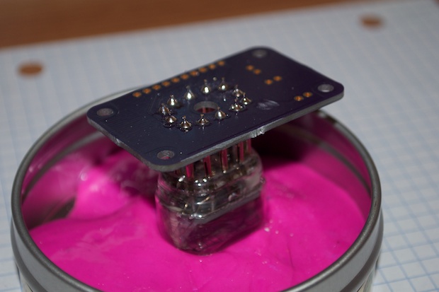
This was a quick 15-minute build. Rev 2 is definitely nicer than rev 1. It’s even a little bit smaller.
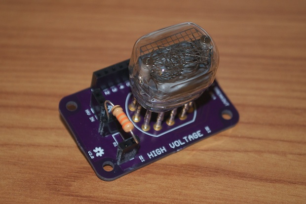
I connected the breakout to my breadboard and powered it up.
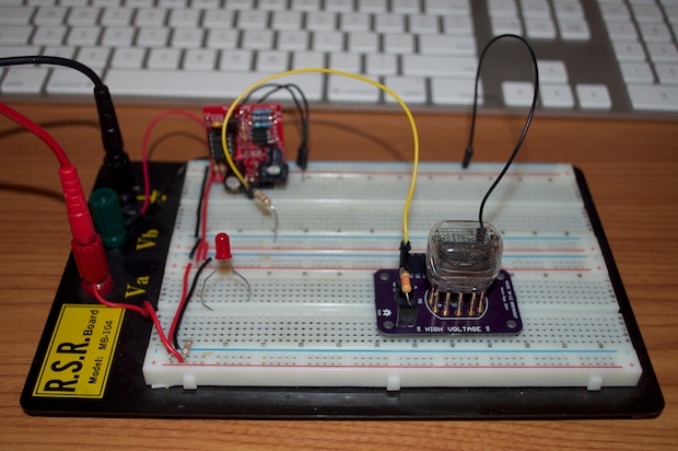
Boom. It works like a charm. I got it right this time. All ten digits light up when the corresponding pin is grounded on the 10-pin header.
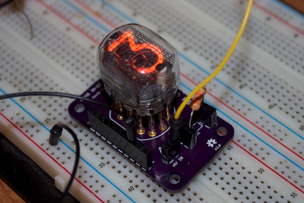
OK, now I can start prototyping...
See this project from start to finish: Nixies! Got My Nixies Powered! IN-12 Nixie Breakout Board, Part 1 Flashing a Nixie with an Arduino IN-12 Nixie Breakout Board, Part 2
Driving a Nixie with a 74141 BCD Decoder More Nixie Tube Experiments Nixie Clock 5V / 12V Power Supply Nixie Clock PCBs / EAGLE Upgrade Nixie Clock Main Board PCB Build Nixie Clock Final Build, Part I Nixie Clock Final Build, Part II Nixie Clock Final Build, Part III Clock Button Panels


