I admit it: I'm a total geek. I love electronics, programming, 3D printing, 3D art, and vintage Apple hardware. I'm always juggling half a dozen projects. I also enjoy documenting it all: my successes, my failures, my experiences... and everything geeky along the way.
SparkFun's FTDI Basic Programmer | Kevin Rye.net - Main
Once my MEGA MINI PCBs arrive, I’m going to need a way to upload sketches to them. I plan on using the MEGA MINI as a test-bed for my GPS clock. I’ve never soldered or in-circuit programmed an ATmega2560 before. I’d hate to waste $100 worth of tech assembling the GPS clock for it to not work. So I want to make something simple as sort of a practice run.
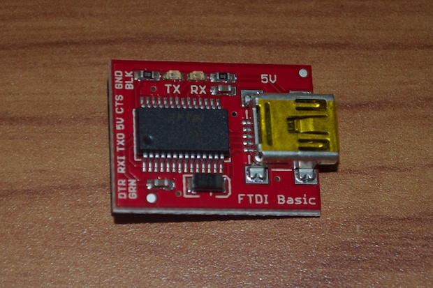
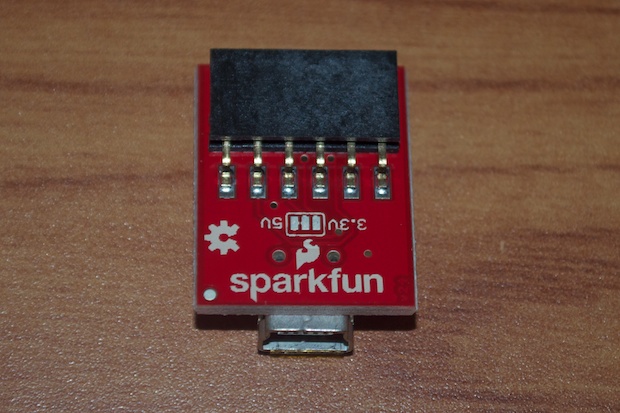
In order to program the board, I’ll need an FTDI programmer. I picked up SparkFun’s FTDI Basic Breakout board for $15 bucks.
It’s a simple little thing, but it’ll allow me to upload sketches without the use of an Arduino. With such a small amount of components, it’s easy to imagine just including the whole design directly into the final project.
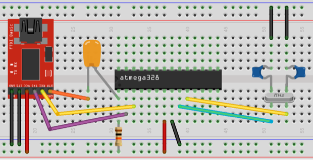
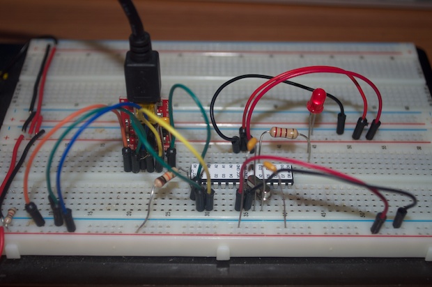
Connect Vcc and ground from the FTDI programmer to the ATmega
Ground CTS on the FTDI programmer
Connect the TX and RX lines of the FTDI programmer to their respective pins on the ATmega
Pull the ATmega’s reset pin high through a 10K pull-up resistor
Connect the FTDI programmer’s DTR pin to the ATmega’s Reset pin through a 0.10 uF cap
You should have something that looks like this:
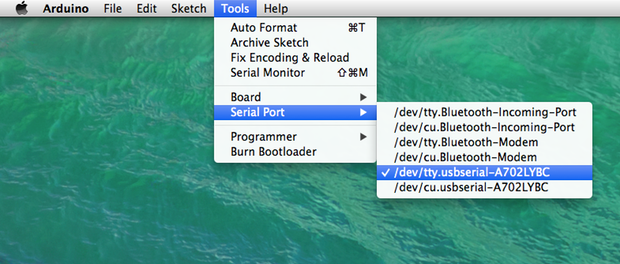
I thought I’d have to install drivers or something, but my Mac seemed to pick it right up. On the Arduino IDE’s Tools > Serial Port menu, the FTDI programmer appeared as soon as I plugged it in. I also chose Arduino Uno as my target board.
With everything connected and configured, I uploaded the Blink sketch.
It’s really fast. It loaded the Blink Sketch in about a second. You’ll see the TX/RX LEDs blink and then pin 13 starts to blink almost immediately.
That’s one more obstacle overcome. Next up will be trying to figure out how to write the bootloader to an ATmega2560. I already ordered an AVR Programmer for that, but I won’t be able to do anything with it until my PCBs arrive in the mail.