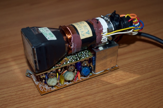
Now that I know I can display my own custom time and date on this
camcorder CRT, it's time to get serious about a PCB and a 3D-printed case.
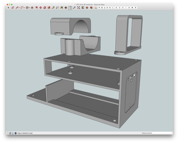
I jumped into SketchUp and started to design something of an enclosure that would house the CRT and the PCB. The PCB does not have any mounting holes, so I'll have to make something that can hold it in place without it falling out or moving around. It also needs to hold the CRT in place and provide some cable management.
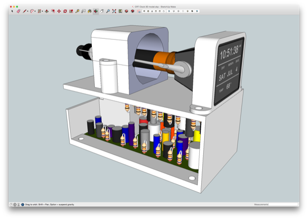
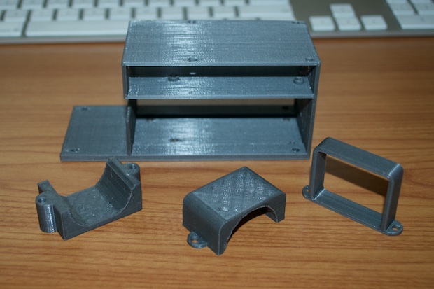
I made it out of 4 separate parts. They will all screw together with 4-40 screws. I want to print the final version in gray, but I'll have to order a new roll of PLA. For now, I'll print the prototype in white.
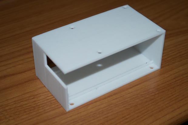
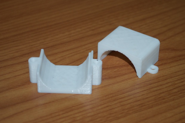
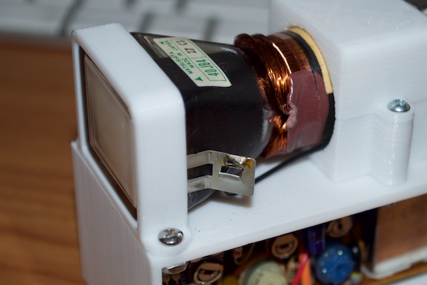
Not bad for a first run.
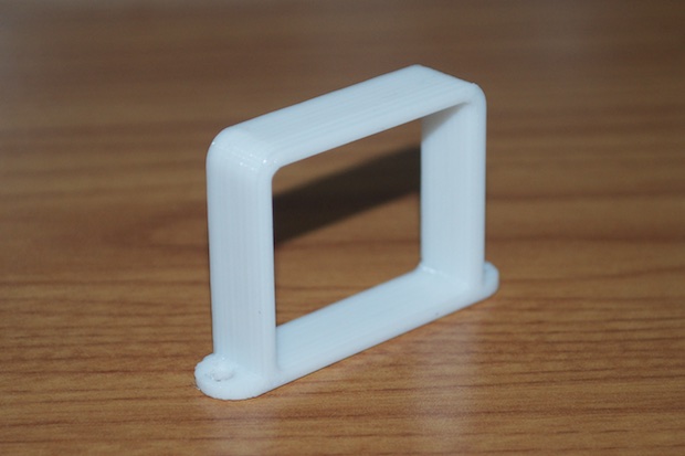
I nailed the cutout for the yoke. It's perfect.
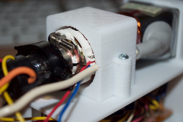
The frame for the CRT isn't bad either. There appears to be a little gap on the right-hand side of the display, but it's intentional.
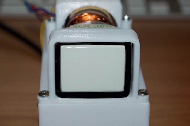
There's just enough room there to tightly squeeze in the ground plate so that it makes good contact with the CRT.
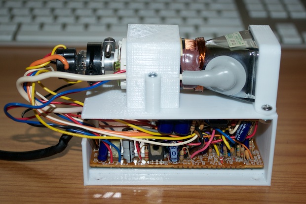
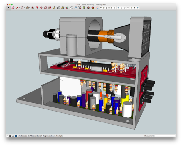
That looks great, but I need to figure out where my controller board is going to go. I'll also need to make some kind of button board so that I can set the time and date. I pictured the controller board being mounted underneath the CRT assembly, with the button board mounted on top of the enclosure. Something like this:
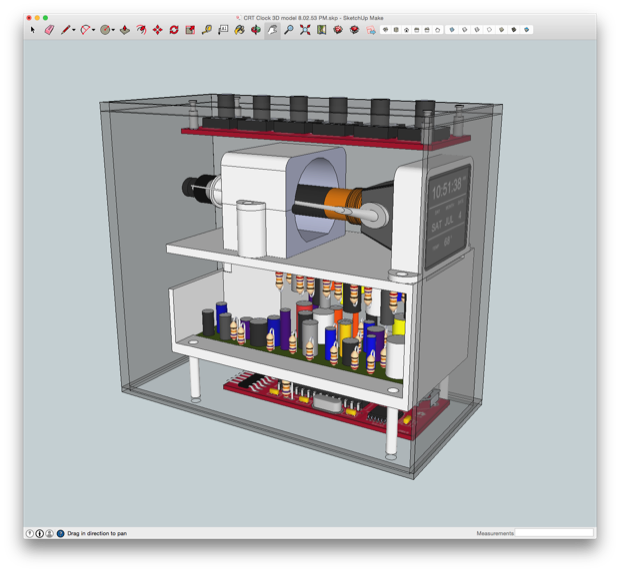
I'll be able to set the time and date with the buttons on top, and maybe throw in a mode button for something extra.
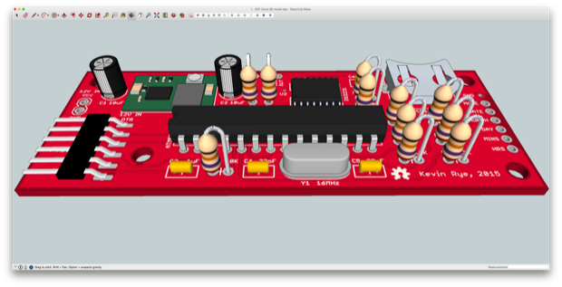
I started to also put together a PCB for the controller, but the more I played around with it, the more it made sense to mount the PCB on top of the CRT PCB.
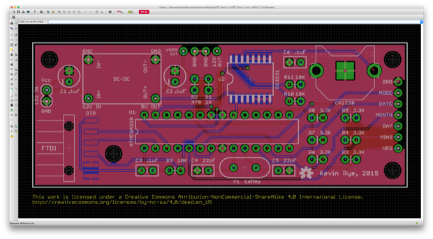
I made a 3D model so that I could figure out where the mounting holes in the frame would go.
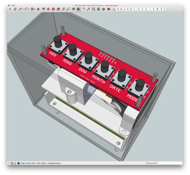
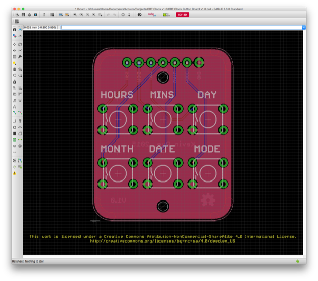
As far as the button board goes, it also made more sense to more the buttons to the front of the entire assembly. I don't want to put anything on top of the CRT. I want that to sit at the top of the completed assembly unobstructed. I also chose to shrink the PCB down considerably from the original design. I chose to use the same footprint from my
Mini Breadboard I/O board. I just added some mounting holes to it.
Again, I created a 3D model so that I could build in some mounting holes to the frame.
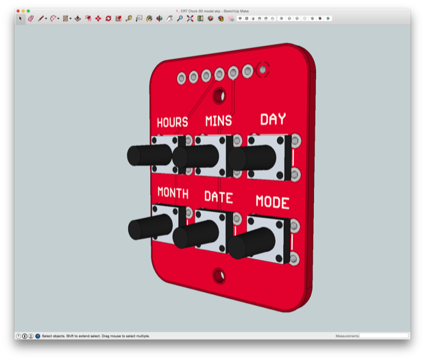
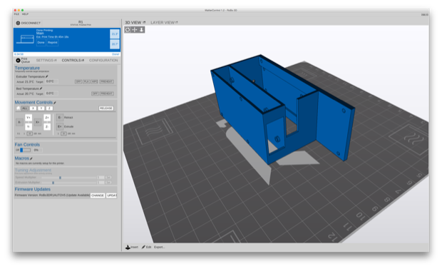
After I incorporated the two new PCBs, it was ready to be printed.

I separated the model into its individual parts and exported them as STL files. All I needed was a new roll of gray PLA.
A few days later my PLA arrived, and off to the printer the parts went.
About 8 or 9 hours later, I had some pretty sweet looking prints.
I can't wait for the PCBs to arrive!
See this project from start to finish: CRT Clock, Part I CRT Clock, Part II CRT Clock, Part III
CRT Clock, Part IV CRT Clock Case
